
I’ve been exploring using Adafruit Stemma QT to create really cool DIY prototypes without any soldering here on the site. It allows you to very quickly throw together prototypes and do testing for various ideas.
I recently ordered a bunch of new Stemma QT devices including the Adafruit ESP32-S3 Reverse TFT Feather and a MLX90640 IR camera module that I wanted to turn into a DIY thermal camera. I wanted it to be small and battery powered.
In this guide I’ll show you the parts I used to build it as well as the code. Let’s get started!
Hardware Used
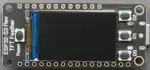
The Adafruit ESP32-S3 Reverse TFT Feather has a built in screen, a Stemma QT port for connecting to other accessories as well as a integrated battery charging and monitoring circuit
Links: Amazon.com*, Adafruit.com*
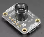
A camera module using the MLX90640 sensor. Uses Stemma QT for plug and play with other Stemma QT / 4-pin I2C devices.
Links: Amazon.com*, Adafruit.com
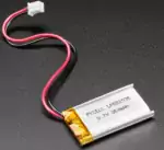
A 350 mAh from Adafruit that will come with the right polarity for the ESP32-S3 Reverse TFT Feather (and is a little bit smaller than the Feather)
Links: Adafruit.com
Overview
First let’s take a look at all of the parts that make up the build:
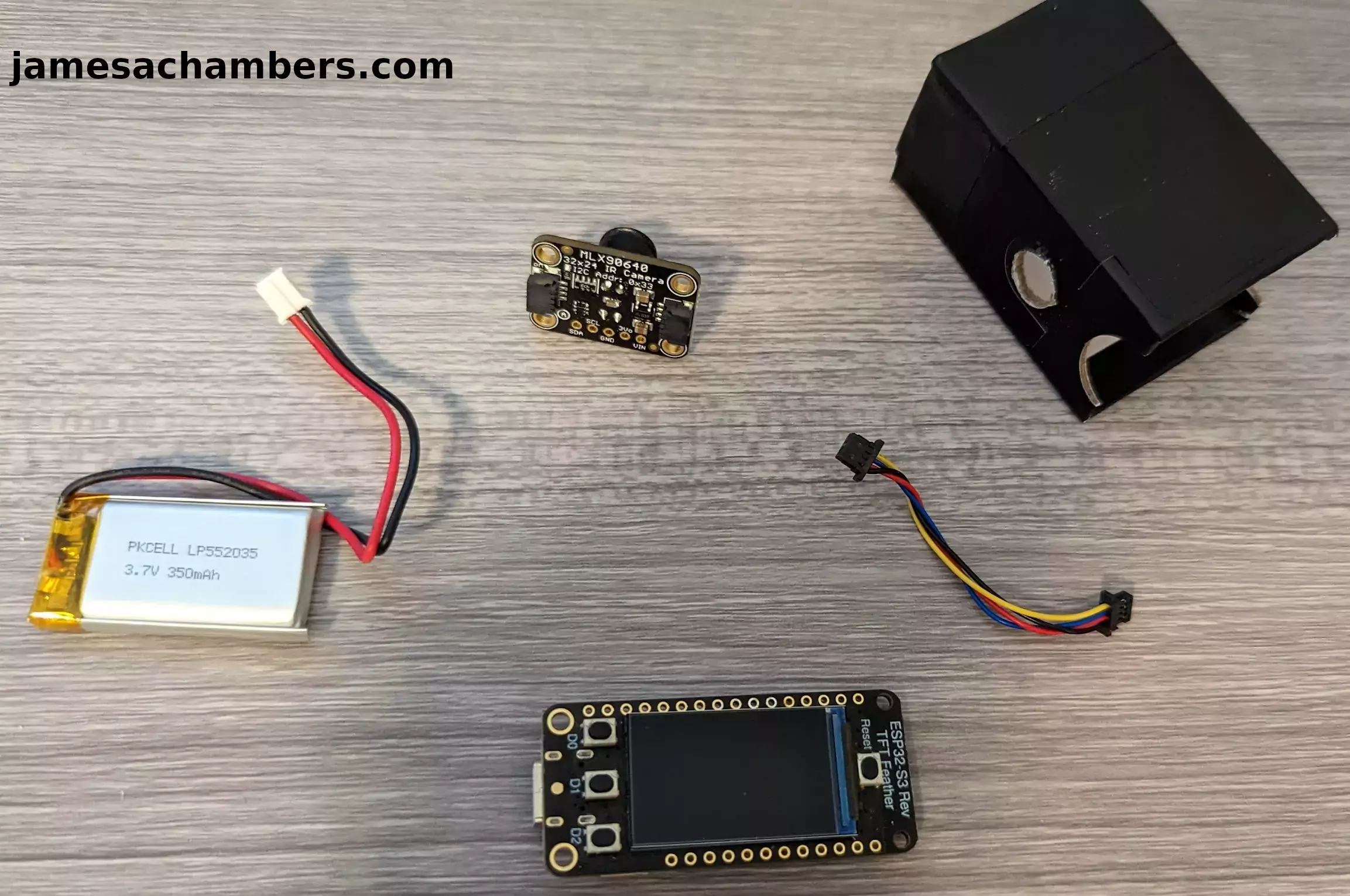
I basically have a small Adafruit 350mAh battery. You can use larger batteries if you would like. I just wanted to use one that was relatively the same size as the ESP32-S3 Reverse TFT feather itself and this was a good size for that.
You don’t have to use a battery from Adafruit but I highly recommend it because otherwise sometimes the batteries will come with the wrong polarity (meaning the red and black wires are switched). Connecting a battery with the wrong polarity is one of the most common ways that beginners destroy their boards. The damage is catastrophic even from doing it once. I’ve done it before on a XAIO expansion board (and yes it killed it, several LEDs stopped working immediately and it kind of half worked for a while but eventually did die altogether with a nasty pop) so be careful with the battery polarity.
Other than that I literally just used a cardboard box I had laying around that looked small enough. You could definitely 3D print something as well but I thought it would be fun to reuse some old packaging instead to make the project with. It’s certainly more environmentally friendly.
This is all you need. There is no soldering. You don’t even need a box if you don’t want to. You can just use the camera module loose as well:
It’s fine. Not a problem at all. This is why I love the Adafruit Stemma QT line of gear so much. You can just plug and play all sorts of different components like this and really quickly break them down and reuse them whenever you’d like.
Now let’s get started configuring it!
Installing CircuitPython & Libraries
First head to the download page for the ESP32-S3 Reverse TFT Feather here. Download the latest version as a .uf2. At time of writing that is 8.0.3.
Next grab the latest Adafruit CircuitPython libraries at this page here. Download the Adafruit bundle for 8.x.
Now we need to connect the Adafruit ESP32-S3 to your computer via USB and put it into boot loader mode.
To put it in the right mode press the reset button and then press the “D0” button twice really quickly (which D0 is also the “BOOT” button on the ESP32-S3 reverse feather, it serves a dual purpose). If you did it right you should see this screen:
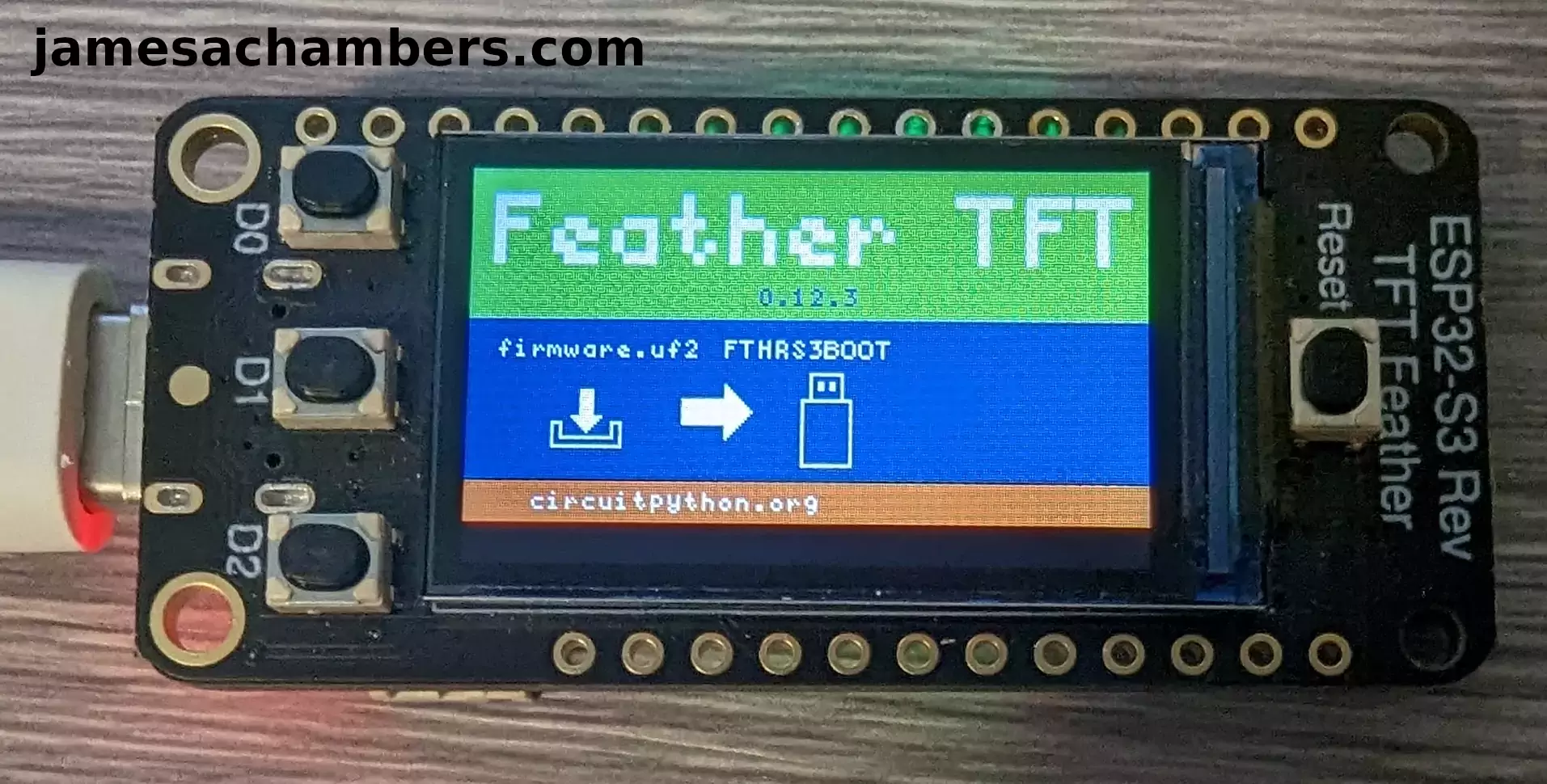
If you see that screen then you should see a new drive on your computer. Drag the .uf2 file we downloaded earlier onto the drive like this:
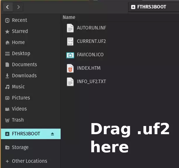
Once it is finished the device should restart. If it doesn’t (and you’re sure it’s finished installing) then unplug the device and plug it back in. You should now see a “CIRCUITPY” drive.
Now we are going to extract the .zip file you downloaded earlier with the Adafruit CircuitPython libraries. Extract the folder and inside there should be a lib folder:
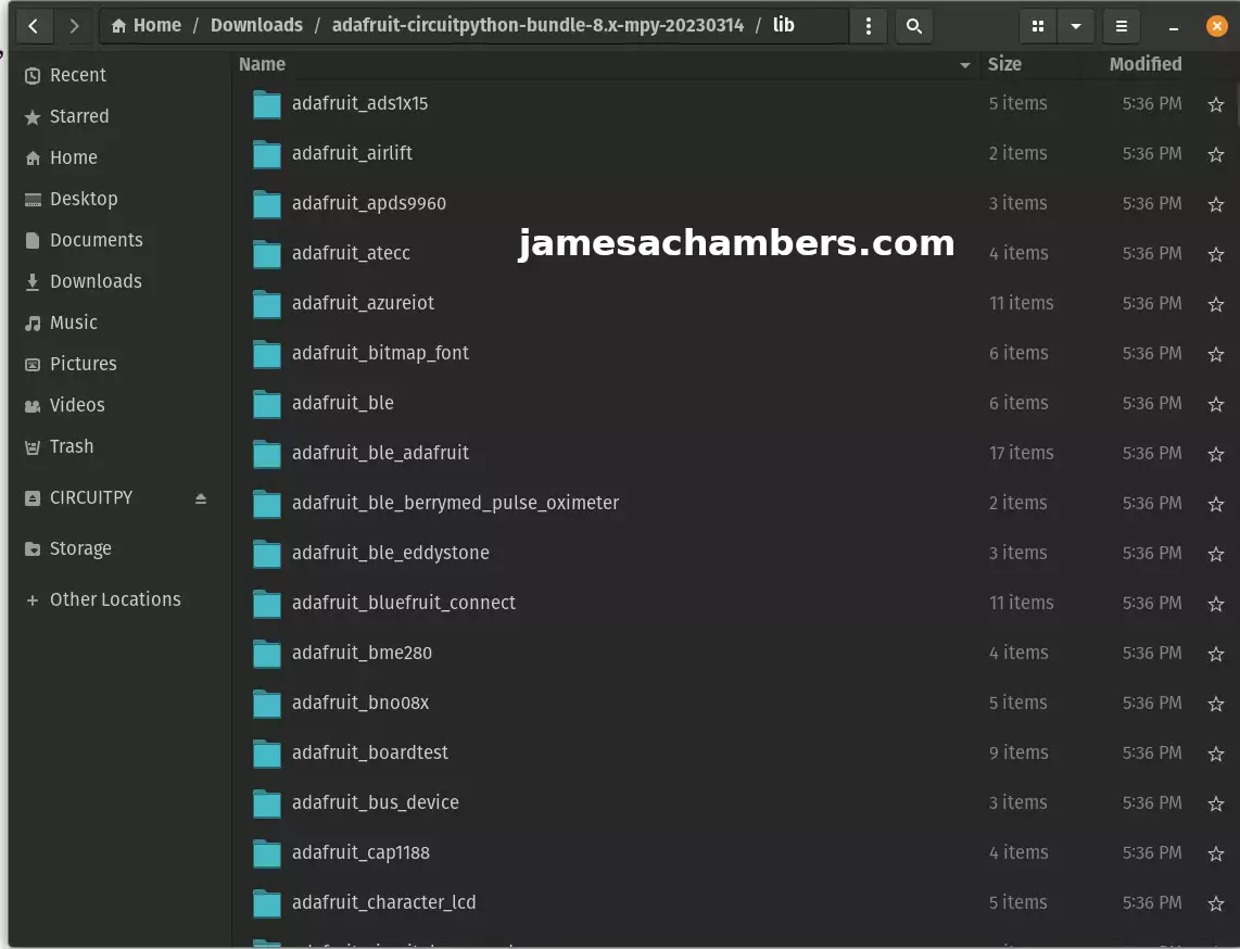
We are going to copy all of these files onto the CIRCUITPY drive. It should already have an empty “lib” folder (if it doesn’t create it).
Copy all of these files from inside the “lib” folder to the CIRCUITPY “lib” folder. Once it’s finished you’re ready to update the code!
Python Code
Now open code.py from the CircuitPython drive. Use the following code:
import time
import board
import busio
import displayio
import terminalio
from adafruit_display_text.label import Label
from simpleio import map_range
import adafruit_mlx90640

number_of_colors = 64  # Number of color in the gradian
last_color = number_of_colors - 1  # Last color in palette
palette = displayio.Palette(number_of_colors)  # Palette with all our colors

color_A = [
    [0, 0, 0],
    [0, 0, 255],
    [0, 255, 255],
    [0, 255, 0],
    [255, 255, 0],
    [255, 0, 0],
    [255, 255, 255],
]
color_B = [[0, 0, 255], [0, 255, 255], [0, 255, 0], [255, 255, 0], [255, 0, 0]]
color_C = [[0, 0, 0], [255, 255, 255]]
color_D = [[0, 0, 255], [255, 0, 0]]

color = color_B
NUM_COLORS = len(color)


def MakeHeatMapColor():
    for c in range(number_of_colors):
        value = c * (NUM_COLORS - 1) / last_color
        idx1 = int(value)  # Our desired color will be after this index.
        if idx1 == value:  # This is the corner case
            red = color[idx1][0]
            green = color[idx1][1]
            blue = color[idx1][2]
        else:
            idx2 = idx1 + 1  # ... and before this index (inclusive).
            fractBetween = value - idx1  # Distance between the two indexes (0-1).
            red = int(
                round((color[idx2][0] - color[idx1][0]) * fractBetween + color[idx1][0])
            )
            green = int(
                round((color[idx2][1] - color[idx1][1]) * fractBetween + color[idx1][1])
            )
            blue = int(
                round((color[idx2][2] - color[idx1][2]) * fractBetween + color[idx1][2])
            )
        palette[c] = (0x010000 * red) + (0x000100 * green) + (0x000001 * blue)


MakeHeatMapColor()

# Bitmap for colour coded thermal value
image_bitmap = displayio.Bitmap(32, 24, number_of_colors)
# Create a TileGrid using the Bitmap and Palette
image_tile = displayio.TileGrid(image_bitmap, pixel_shader=palette)
# Create a Group for scaling
image_group = displayio.Group(scale=5)
image_group.append(image_tile)

scale_bitmap = displayio.Bitmap(1, number_of_colors, number_of_colors)
# Create a Group Scale must be 128 divided by number_of_colors
scale_group = displayio.Group(scale=2)
scale_tile = displayio.TileGrid(scale_bitmap, pixel_shader=palette, x=115, y=0)
scale_group.append(scale_tile)

for i in range(number_of_colors):
    scale_bitmap[0, i] = i  # Fill the scale with the palette gradian

# Create the super Group
group = displayio.Group()

min_label = Label(terminalio.FONT, color=palette[0], x=198, y=5)
max_label = Label(terminalio.FONT, color=palette[last_color], x=198, y=120)

# Add all the sub-group to the SuperGroup
group.append(image_group)
group.append(scale_group)
group.append(min_label)
group.append(max_label)

# Add the SuperGroup to the Display
board.DISPLAY.show(group)

min_t = 20  # Initial minimum temperature range, before auto scale
max_t = 37  # Initial maximum temperature range, before auto scale

i2c = busio.I2C(board.SCL, board.SDA, frequency=800000)

mlx = adafruit_mlx90640.MLX90640(i2c)
print("MLX addr detected on I2C")
print([hex(i) for i in mlx.serial_number])

# mlx.refresh_rate = adafruit_mlx90640.RefreshRate.REFRESH_2_HZ
mlx.refresh_rate = adafruit_mlx90640.RefreshRate.REFRESH_4_HZ

frame = [0] * 768

while True:
    stamp = time.monotonic()
    try:
        mlx.getFrame(frame)
    except ValueError:
        # these happen, no biggie - retry
        continue

    #    print("Time for data aquisition: %0.2f s" % (time.monotonic()-stamp))

    mini = frame[0]  # Define a min temperature of current image
    maxi = frame[0]  # Define a max temperature of current image

    for h in range(24):
        for w in range(32):
            t = frame[h * 32 + w]
            if t > maxi:
                maxi = t
            if t < mini:
                mini = t
            image_bitmap[w, (23 - h)] = int(map_range(t, min_t, max_t, 0, last_color))

    min_label.text = "%0.2f" % (min_t)

    max_string = "%0.2f" % (max_t)
    max_label.text = max_string

    min_t = mini  # Automatically change the color scale
    max_t = maxi
I adapted this from the official Adafruit documentation here and updated it for this board (and made a few other changes).
Conclusion
It actually functions really well! I’m not sure what the battery life is but I’ve left it on for at least 30-45 minutes without it dying. I’m guessing with a larger battery it would last an incredibly long time (relatively speaking).
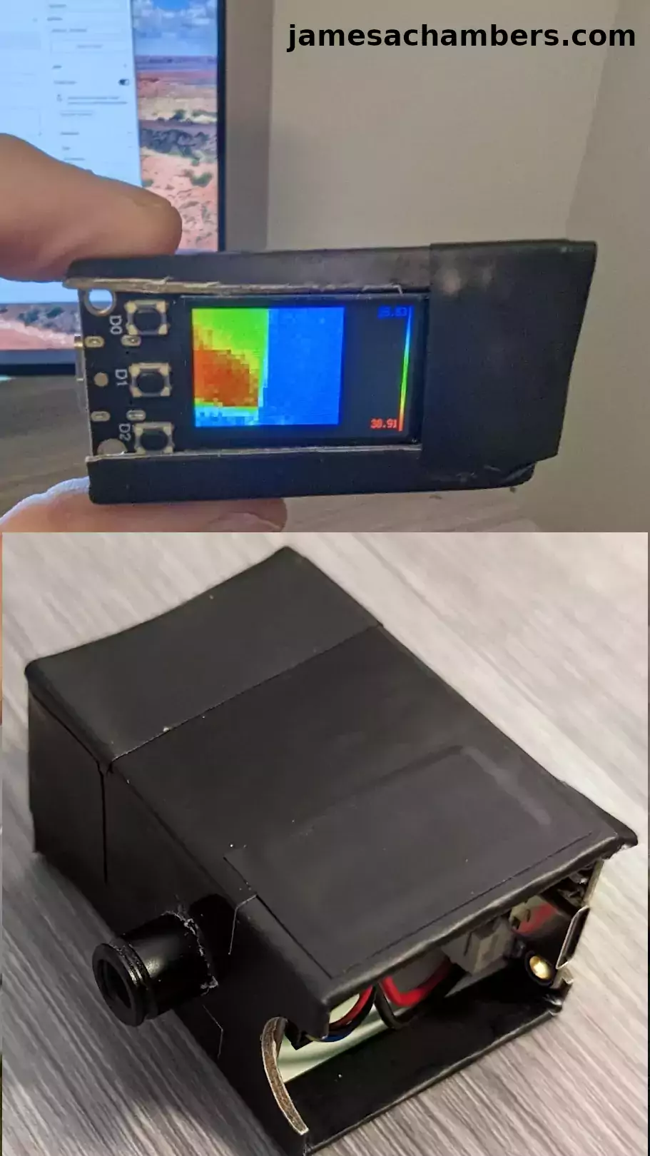
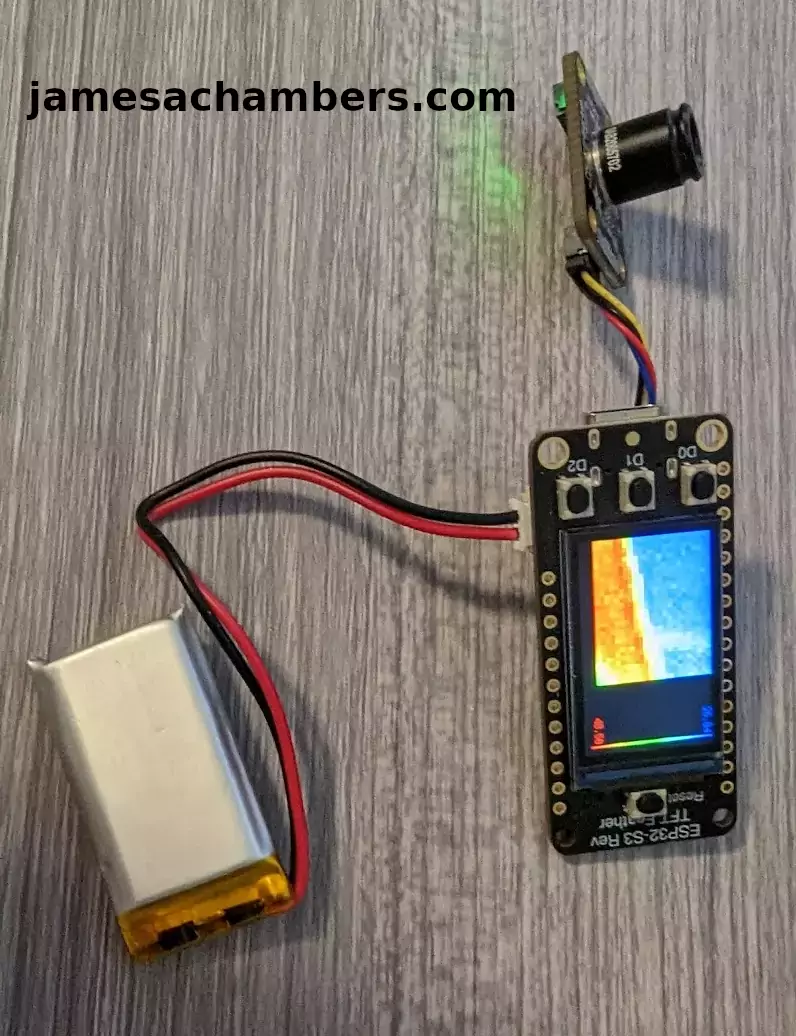
Here’s an action shot:
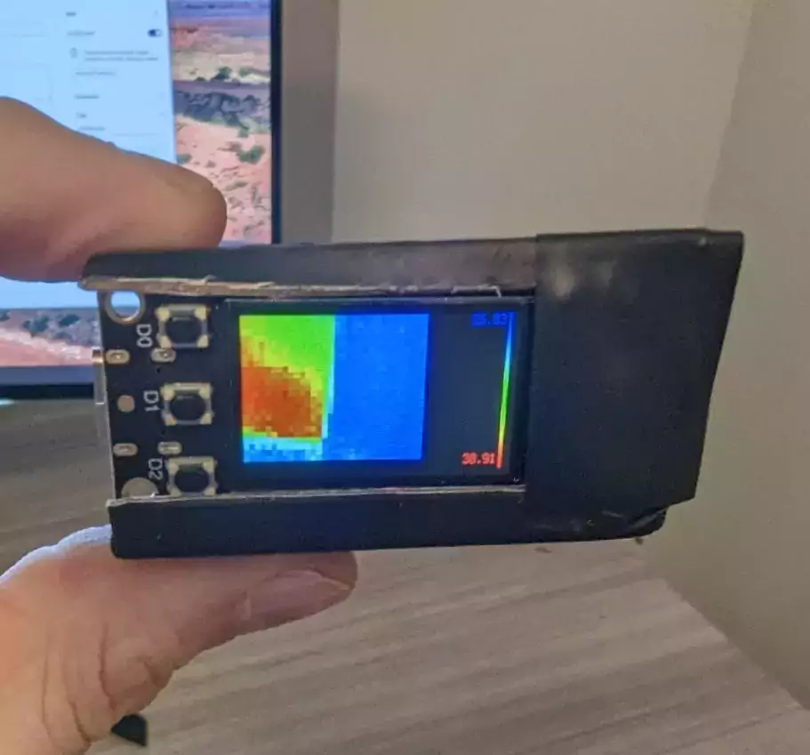
Here you can clearly see the edge of the monitor (which is hot) against the back of my wall (cool). It shows you the temperature scales on the right hand side. These automatically adjust based on the sources within a sliding window.
This was my first try with CircuitPython and I honestly liked it. I’ll definitely be doing more projects with the language here on the site. Stay tuned!
Other Resources
Don’t miss my guide on other Adafruit Stemma QT devices and using them with Arduino here
I’ve also made a Adafruit IoT button project that can be used in Home Assistant here


Hi James,
Thanks for sharing this neat DIY tutorial using some new kit from Adafruit as the Thermal Camera module looks more than capable and fairly priced when you compare it with more industrial styled cameras. Also nice to see you running the commands in CircuitPython as its heavily supported by Adafruit and fairly simple to use.
I’m hoping Adafruit manage to keep the Adafruit ESP32-S3 Reverse TFT Feather restocked as the first few batches sold out quickly and from what I can gather nobody else has stock for sale so I’m relying on a local seller in Australia otherwise shipping ends up costing way too much from USA>AUS and my last order took a bit longer to arrive.
I look forward to seeing future projects utilising the TFT as the ESP32-S3 chip is quite powerful and I see Seeed just announced a future XIAO ESP32-S3 Sense camera dev board that looks very promising and has onboard wireless and upgradable camera lenses which is frankly insane when you consider the capabilities of the ESP32-EYE and various clone CAM boards for their footprint and the XIAO board is no bigger than the actual camera module… Take care!
Hey Razor Burn,
Thanks so much, the thermal camera has been really interesting! I used the (more) expensive module for this one but they do have a less expensive one called the AMG8833. I did get one of these but it’s only a 8×8 sensor while this one is a 24×32 sensor. You can imagine how big 8×8 would be blown up on that screen vs. the 24×32.
That doesn’t mean the AMG8833 won’t have it’s uses and I’ll definitely be doing some coverage on it. For a tiny handheld battery powered camera though you’d want the higher level of detail / additional sensors. I got the 55 degree one but there’s also a 110 degree one that is a much wider shot even still. That one might be even better for something like a handheld camera depending on what kind of things you’d want to be measuring with it.
I’m pretty happy with the 55 degree FoV (field of view) as realistically I’m looking for hotspots on devices / around the room from a few feet to maybe up to a dozen feet away or so (not too different from what I was showing in the picture). If you wanted to observe wider areas you’d probably want to go for the 110 degree FoV and get the wider shot. It will just come down to what people intend to use it for. Both of them have exactly the same number of 24×32 sensors so the advantage of the 55 degree FoV is that it packs a bit more detail / granularity in the image (in a more focused shot). The 110 degree FoV will show you a wider area but in not quite as fine of detail.
That is unfortunate news about the supply situation for these. They have been hard to get your hands on and the shipping makes things even more tricky. I’m sure you could get the S2 version (and probably through a local reseller even maybe?) but I know how you feel about the older modules. They really do make a good Stemma QT jump point. If it comes down to you can get one of those without paying US to AUS shipping (and can get that one through the local reseller) it might be worth it. It’s essentially a Stemma QT / Grove / 4-pin I2C jumping point with a screen built in. Normally I’d say go for the newer S3 version no matter what since they are the same price for people in the US. For you though it may end up being substantially cheaper if you can get a local reseller version of a S2.
That’s very interesting about the Seeed Studios camera module. I had not seen that announcement yet but I have been getting a bunch of product announcement / event emails lately so I think we’re going to continue to see more products from them over the near future. We definitely do need a S3 generation of cameras. I did order a LILYGO version with S3 and a pretty big illumination light. I ordered the last one ($20 + $9 shipping for a total of $29) and it now says unavailable so that’s not very encouraging but it won’t come until April it said so hopefully it restocks by then. I definitely will look into getting one of the XAIO ones as well.
Thanks and take care!