
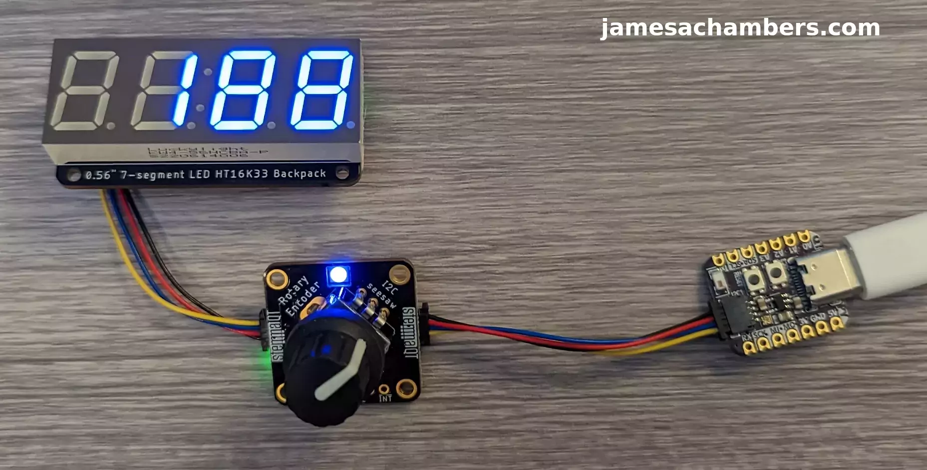
I’ve been doing a lot of coverage of ESP32-related chips lately on the site. One thing that is a bit painful with them though is that they usually require a lot of soldering. That’s why I find the Adafruit QT Py series of ESP32 chips so exciting. They eliminate the soldering!
Unfortunately once I got all of my parts and tried to get started I ran into several issues that are not covered at all (or very poorly covered) by the official documentation and guides available. None of the things I’m going to cover were particularly difficult once you know what they are and how to address them. I did however lose days or closer to a week of time messing with this as I had to figure it all out from piecing together scraps here and there from forum posts.
In this guide I’ll show you how to get Arduino working with the Adafruit QT Py boards using Stemma and how to avoid all the pitfalls that I lost a lot of time on getting started. Let’s begin!
Hardware Used
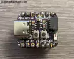
The Adafruit QT Py ESP32-C3 is an incredibly tiny board that has WiFi/Bluetooth capabilities and is powered through USB-C
Links: Adafruit.com, Amazon.com*
The Adafruit rotary encoder is Stemma QT enabled giving a reliable and nice rotary encoder with a RGB LED (NeoPixel) on board!
Links: Adafruit.com
The Adafruit 7 segment display is an excellent display available in multiple colors
Links: Adafruit.com
Getting Arduino 2.X
Now let’s start with the first major problem I ran into. I was trying to use Arduino installed from my Linux distribution’s apt repositories. This gives me Arduino version 1.8.19.
It turns out that if you use a 1.x version of Arduino you will get *crazy* errors when trying to use the Wire1 object within Arduino that is required to use Stemma QT’s connector within the Arduino code.
For Linux this comes as a file with a .AppImage extension. Do a:
chmod +x arduino-ide_2.3.8_Linux_64bit.AppImage
./arduino-ide_2.3.8_Linux_64bit.AppImage
If you get an error about sandboxing I recommend disabling it for development purposes with:
./arduino-ide_2.3.8_Linux_64bit.AppImage --no-sandboxThis should fire the Arduino IDE right up!
Adding Adafruit Boards
To add the Adafruit boards to the Arduino IDE we’re going to add the latest version of the ESP32 board packages. To do this go to “File” and then “Preferences”.
You should see the “Additional boards manager URLs” at the bottom of the page:
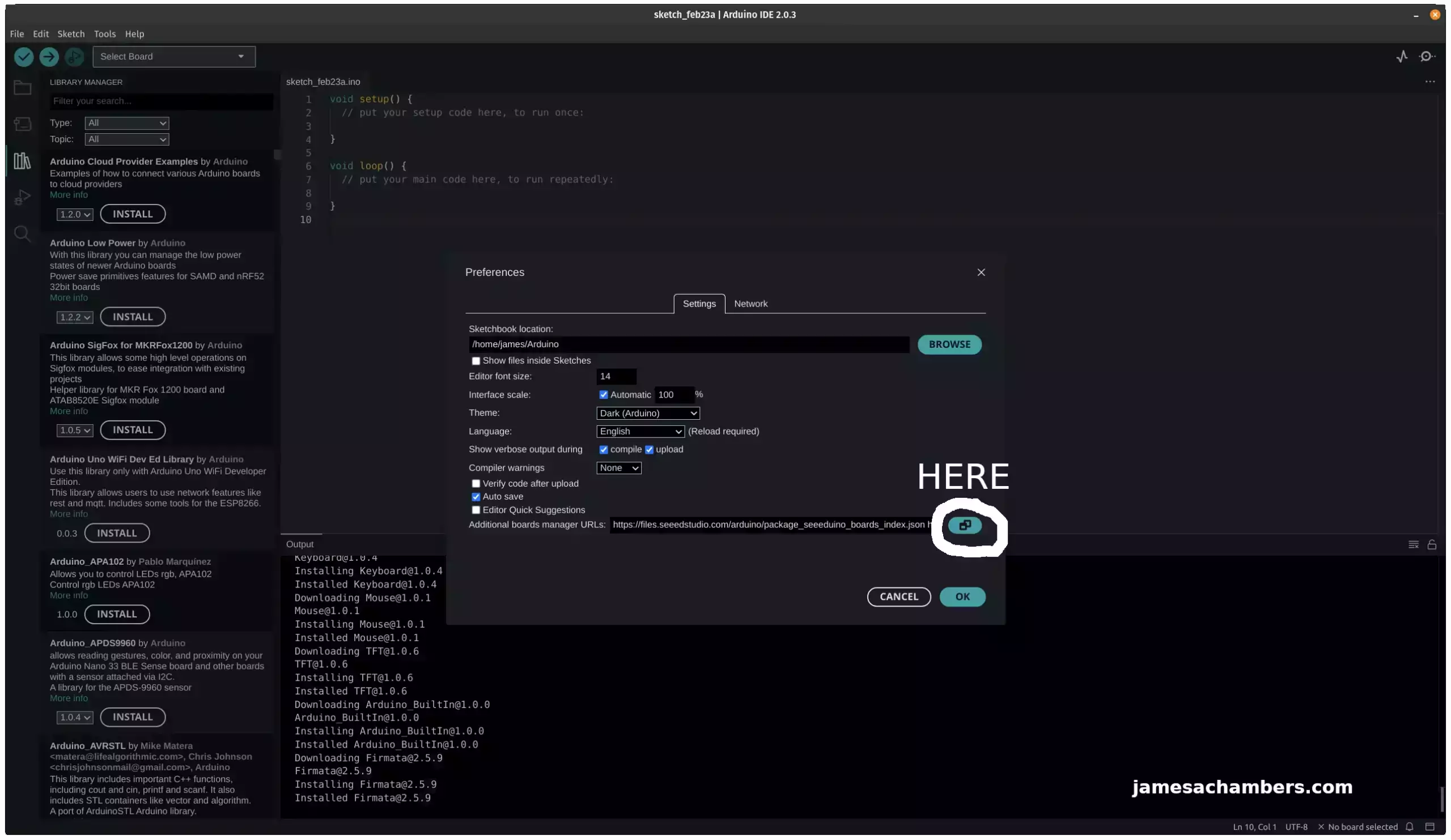
Once you click the above icon add the following URL:
https://raw.githubusercontent.com/espressif/arduino-esp32/gh-pages/package_esp32_dev_index.json
Press “OK” to save.
Now you should be able to click the “Select Board” box in the top left. Click the serial port for your board plugged into your PC. That should take you to this screen:
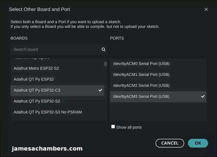
Select your correct QT Py from the list and press OK. Your Arduino environment is now configured!
You may need some additional libraries installed as we proceed. Those can be installed in the “Library Manager” which is visible in the screenshot right before the one above on the left hand side of the screen. These will depend on exactly what components you are using. For this guide I installed the Adafruit “seesaw” library for the rotary encoder and the Adafruit “LED Backpack Library” for the 7 segment display.
Fixing Adafruit 7 Segment Display for Stemma QT
If you’ve already got this far then you probably know that if you run the Adafruit documentation for any of the Stemma QT components it basically will just do nothing. That’s because all of the documentation I’ve seen isn’t actually written for Stemma QT and is written for people who are still soldering everything together.
Here’s what the documentation says for the simple 7 segment display example:
#include <Wire.h> // Enable this line if using Arduino Uno, Mega, etc.
#include <Adafruit_GFX.h>
#include "Adafruit_LEDBackpack.h"

Adafruit_7segment matrix = Adafruit_7segment();

void setup() {
  Serial.begin(9600);
  Serial.println("7 Segment Backpack Test");
  matrix.begin(0x70);
}

void loop() {
  // print a hex number
  matrix.print(0xBEEF, HEX);
  matrix.writeDisplay();
  delay(500);
}
The reason this example won’t work is because by default Arduino will use Wire for the I2C interface and Stemma QT actually uses Wire1.
To fix this we actually need to pass Wire1 to the matrix.begin(0x70) code like this:
matrix.begin(0x70, &Wire1);
That makes the final updated code for this easy example this:
#include <Wire.h> // Enable this line if using Arduino Uno, Mega, etc.
#include <Adafruit_GFX.h>
#include "Adafruit_LEDBackpack.h"

Adafruit_7segment matrix = Adafruit_7segment();

void setup() {
  Serial.begin(9600);
  Serial.println("7 Segment Backpack Test");
  matrix.begin(0x70, &Wire1);
}

void loop() {
  // print a hex number
  matrix.print(0xBEEF, HEX);
  matrix.writeDisplay();
  delay(500);
}
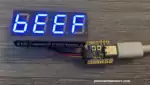
This code should compile if you are using Arduino 2.X. If you are using Arduino 1.X you may get some strange compilation errors such as “index is out of range”. The result should be this:
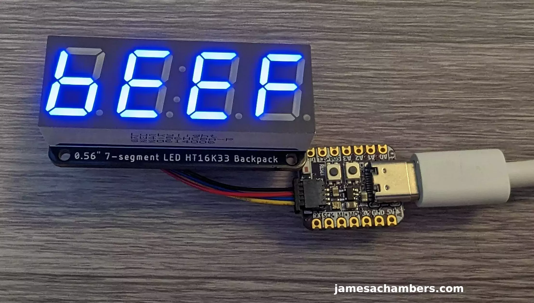
Boom! You now have a solderless 7-segment display. It’s a little bit easier to see that it says “b33F” in person as my camera picked up the white of the unilluminated parts of the screen really well for some reason. It’s really obvious in person that’s what it says!
Fixing Adafruit Rotary Encoder for Stemma QT
Now you might think it’s as easy as passing the Wire1 object to update any code. You are correct but unfortunately passing it is not always done the same way. Let’s look at the Adafruit rotary encoder example which was much tougher for me to update:
#include "Adafruit_seesaw.h"
#include <seesaw_neopixel.h>

#define SS_SWITCH        24
#define SS_NEOPIX        6

#define SEESAW_ADDR          0x36

Adafruit_seesaw ss;
seesaw_NeoPixel sspixel = seesaw_NeoPixel(1, SS_NEOPIX, NEO_GRB + NEO_KHZ800);

int32_t encoder_position;

void setup() {
  Serial.begin(115200);
  while (!Serial) delay(10);

  Serial.println("Looking for seesaw!");

  if (! ss.begin(SEESAW_ADDR) || ! sspixel.begin(SEESAW_ADDR)) {
    Serial.println("Couldn't find seesaw on default address");
    while(1) delay(10);
  }
  Serial.println("seesaw started");

  uint32_t version = ((ss.getVersion() >> 16) & 0xFFFF);
  if (version  != 4991){
    Serial.print("Wrong firmware loaded? ");
    Serial.println(version);
    while(1) delay(10);
  }
  Serial.println("Found Product 4991");

  // set not so bright!
  sspixel.setBrightness(20);
  sspixel.show();

  // use a pin for the built in encoder switch
  ss.pinMode(SS_SWITCH, INPUT_PULLUP);

  // get starting position
  encoder_position = ss.getEncoderPosition();

  Serial.println("Turning on interrupts");
  delay(10);
  ss.setGPIOInterrupts((uint32_t)1 << SS_SWITCH, 1);
  ss.enableEncoderInterrupt();
}

void loop() {
  if (! ss.digitalRead(SS_SWITCH)) {
    Serial.println("Button pressed!");
  }

  int32_t new_position = ss.getEncoderPosition();
  // did we move arounde?
  if (encoder_position != new_position) {
    Serial.println(new_position);         // display new position

    // change the neopixel color
    sspixel.setPixelColor(0, Wheel(new_position & 0xFF));
    sspixel.show();
    encoder_position = new_position;      // and save for next round
  }

  // don't overwhelm serial port
  delay(10);
}

uint32_t Wheel(byte WheelPos) {
  WheelPos = 255 - WheelPos;
  if (WheelPos < 85) {
    return sspixel.Color(255 - WheelPos * 3, 0, WheelPos * 3);
  }
  if (WheelPos < 170) {
    WheelPos -= 85;
    return sspixel.Color(0, WheelPos * 3, 255 - WheelPos * 3);
  }
  WheelPos -= 170;
  return sspixel.Color(WheelPos * 3, 255 - WheelPos * 3, 0);
}
So we actually have two problems to deal with here. The first problem is this Stemma QT expansion board has a NeoPixel AND the rotary encoder. We are going to need to pass Wire1 to both these objects (ss and sspixel).
Now if you are a very logical person like me you might assume that to fix this one we do the exact same thing as the last example. Surely we just add &Wire1 after the ss.begin(SEESAW_ADDR).
Wrong. Remember how I said unfortunately not all of these are the same to update? This one actually goes in the ss constructor like this:
Adafruit_seesaw ss;
*TO*
Adafruit_seesaw ss(&Wire1);
Similarly to fix the NeoPixel we actually need to change the sspixel initialization line to this:
seesaw_NeoPixel sspixel = seesaw_NeoPixel(1, SS_NEOPIX, NEO_GRB + NEO_KHZ800, &Wire1);
That’s it! Your final corrected code should look like this:
#include "Adafruit_seesaw.h"
#include <seesaw_neopixel.h>

#define SS_SWITCH        24
#define SS_NEOPIX        6

#define SEESAW_ADDR          0x36

Adafruit_seesaw ss(&Wire1);
seesaw_NeoPixel sspixel = seesaw_NeoPixel(1, SS_NEOPIX, NEO_GRB + NEO_KHZ800, &Wire1);

int32_t encoder_position;

void setup() {
  Serial.begin(115200);
  while (!Serial) delay(10);

  Serial.println("Looking for seesaw!");

  if (! ss.begin(SEESAW_ADDR) || ! sspixel.begin(SEESAW_ADDR)) {
    Serial.println("Couldn't find seesaw on default address");
    while(1) delay(10);
  }
  Serial.println("seesaw started");

  uint32_t version = ((ss.getVersion() >> 16) & 0xFFFF);
  if (version  != 4991){
    Serial.print("Wrong firmware loaded? ");
    Serial.println(version);
    while(1) delay(10);
  }
  Serial.println("Found Product 4991");

  // set not so bright!
  sspixel.setBrightness(20);
  sspixel.show();

  // use a pin for the built in encoder switch
  ss.pinMode(SS_SWITCH, INPUT_PULLUP);

  // get starting position
  encoder_position = ss.getEncoderPosition();

  Serial.println("Turning on interrupts");
  delay(10);
  ss.setGPIOInterrupts((uint32_t)1 << SS_SWITCH, 1);
  ss.enableEncoderInterrupt();
}

void loop() {
  if (! ss.digitalRead(SS_SWITCH)) {
    Serial.println("Button pressed!");
  }

  int32_t new_position = ss.getEncoderPosition();
  // did we move arounde?
  if (encoder_position != new_position) {
    Serial.println(new_position);         // display new position

    // change the neopixel color
    sspixel.setPixelColor(0, Wheel(new_position & 0xFF));
    sspixel.show();
    encoder_position = new_position;      // and save for next round
  }

  // don't overwhelm serial port
  delay(10);
}


uint32_t Wheel(byte WheelPos) {
  WheelPos = 255 - WheelPos;
  if (WheelPos < 85) {
    return sspixel.Color(255 - WheelPos * 3, 0, WheelPos * 3);
  }
  if (WheelPos < 170) {
    WheelPos -= 85;
    return sspixel.Color(0, WheelPos * 3, 255 - WheelPos * 3);
  }
  WheelPos -= 170;
  return sspixel.Color(WheelPos * 3, 255 - WheelPos * 3, 0);
}
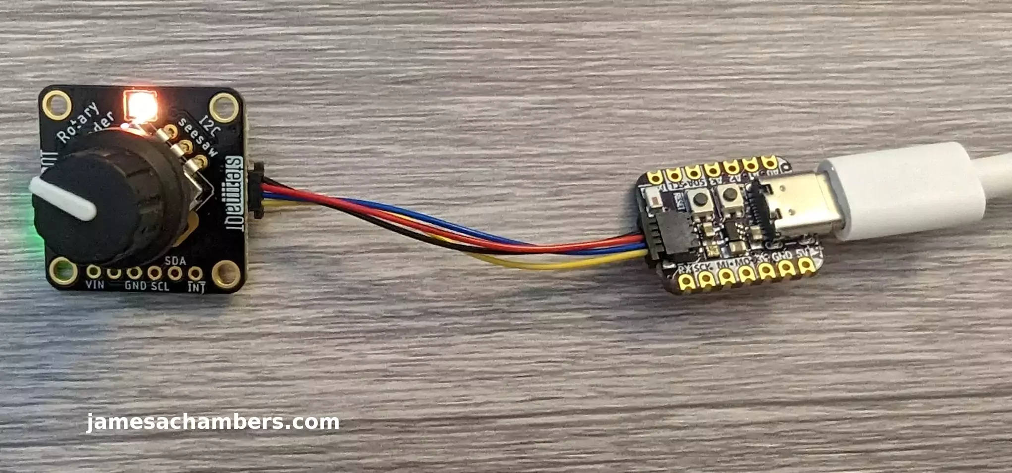
You should have a nice little rotary encoder that changes the NeoPixel color as you turn the knob:
Daily Chaining
Now let’s combine the two examples and daisy chain them. Oh boy, this is going to be a nightmare, right?
Nope, fortunately the hard part is over. The hardest part is just figuring out how to pass the Stemma QT Wire1 object to the various libraries/constructors. You can literally just squish the code from the two together like this:
#include <Wire.h>
#include <Adafruit_GFX.h>
#include "Adafruit_LEDBackpack.h"
#include "Adafruit_seesaw.h"
#include <seesaw_neopixel.h>

#define SS_SWITCH 24
#define SS_NEOPIX 6

#define SEESAW_ADDR 0x36
Adafruit_seesaw ss(&Wire1);
seesaw_NeoPixel sspixel = seesaw_NeoPixel(1, SS_NEOPIX, NEO_GRB + NEO_KHZ800, &Wire1);
int32_t encoder_position;

Adafruit_7segment matrix = Adafruit_7segment();

void setup() {
  Serial.begin(9600);
  matrix.begin(0x70, &Wire1);

  Serial.println("Looking for seesaw!");

  if (!ss.begin(SEESAW_ADDR)) {
    Serial.println("Couldn't find seesaw on default address");
    while (1) delay(10);
  }
  if (!sspixel.begin(SEESAW_ADDR)) {
    Serial.println("Couldn't find seesaw pixel on default address");
    while (1) delay(10);
  }
  Serial.println("seesaw started");

  uint32_t version = ((ss.getVersion() >> 16) & 0xFFFF);
  if (version != 4991) {
    Serial.print("Wrong firmware loaded? ");
    Serial.println(version);
    while (1) delay(10);
  }
  Serial.println("Found Product 4991");

  // set not so bright!
  sspixel.setBrightness(20);
  sspixel.show();

  // use a pin for the built in encoder switch
  ss.pinMode(SS_SWITCH, INPUT_PULLUP);

  // get starting position
  encoder_position = ss.getEncoderPosition();

  Serial.println("Turning on interrupts");
  delay(10);
  ss.setGPIOInterrupts((uint32_t)1 << SS_SWITCH, 1);
  ss.enableEncoderInterrupt();
}

void loop() {
  if (!ss.digitalRead(SS_SWITCH)) {
    Serial.println("Button pressed!");
  }

  int32_t new_position = ss.getEncoderPosition();
  // did we move arounde?
  if (encoder_position != new_position) {
    matrix.println(new_position);
    matrix.writeDisplay();
    delay(10);

    Serial.println(new_position);  // display new position

    // change the neopixel color
    sspixel.setPixelColor(0, Wheel(new_position & 0xFF));
    sspixel.show();
    encoder_position = new_position;  // and save for next round
  }

  // don't overwhelm serial port
  delay(10);
}


uint32_t Wheel(byte WheelPos) {
  WheelPos = 255 - WheelPos;
  if (WheelPos < 85) {
    return sspixel.Color(255 - WheelPos * 3, 0, WheelPos * 3);
  }
  if (WheelPos < 170) {
    WheelPos -= 85;
    return sspixel.Color(0, WheelPos * 3, 255 - WheelPos * 3);
  }
  WheelPos -= 170;
  return sspixel.Color(WheelPos * 3, 255 - WheelPos * 3, 0);
}
That gives the follow result:
In this example the only modification I’ve made is that it will also display the rotary coder’s position on the 7 segment display. It updates as you turn the knob (as does the color of the light still).
Conclusion
Once you get past the initial learning hump of understanding that the idea that the Stemma QT interface is addressed as Wire1 as well as overcoming issues related to having a new enough Arduino version to compile it you can start to see the potential. You can just throw these components together and daily chain them and it’s actually really easy to work with.
I’d encourage Adafruit to update their documentation to include more examples related to Stemma QT addressing via Wire1. I pieced all of this together from forum posts from all over that hinted toward this was what I needed to do and went from there. It wasn’t easy because as I covered it’s not always the same to pass “Wire1” to a library you’re using.
Hopefully these examples help some other people make this simple breakthrough and get started working with their Stemma QT devices. I’d definitely recommend them!
Other Resources
I’ve also covered making an Adafruit IoT button here that can perform actions within Home Assistant!
Adafruit makes a neat USB-C to DC barrel jack power adapter that I’ve reviewed here


Hi James,
I have really been enjoying my Adafruit gear thanks in large part to your insightful guides so when I saw you had some difficulties working out the STEMMA QT I quickly read through hoping you would work it out and thankfully you did so well done. I made sure to update my Arduino IDE as it was an older version just incase so great tip!
The biggest plus in using Adafruit is the ease of use as very minimal soldering which suits me perfectly, the vast range of gear that pairs well with popular brands such as Arduino, Seeed (Grove/XIAO) and Raspberry Pi plus they’re very engaging be it via Youtube, Discord or their Forum which isn’t normally the case with manufactures so I can’t recommend them highly enough!
I share your frustration as the documentation can be a bit of a maze to sort through especially for a newbie like me but for the large part they regularly update things so hopefully they heed your suggestions and get some clearer instructions online as the STEMMA QT range is very popular and designed to be ‘plug & play’ yet you demonstrated some oversight and in the process produced a very detailed guide that will save users time and allow them to enjoy this cool tech gear as it was attended. Keep up the amazing work!
Hey Razor Burn,
Thanks so much! You’re actually completely right about the Adafruit documentation. It’s really good almost all of the time! I think it’s really mostly just a result of there being a lot more boards other than the QT Py from Adafruit use the Stemma QT connector.
In fact one of the boards I want to get my hands on is the Feather TFT ESP32-S3. This has been out of stock since it launched. They have the ESP32-S2 version available but it’s the same price as the new one so I’ve just been waiting for the new one to restock. It has a Stemma QT port as well as a LiPo battery charger port meaning you could connect a backup battery to it like I do my Seeed expansion boards. The color TFT is really nice though as the Seeed one is monochrome.
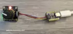
I was able to fix Stemma QT for Home Assistant as well even though I haven’t published that one yet. Take a look at my garage sensor setup:
Should it just be hanging there? No probably not but it’s just a temporary setup. I’d find some way to stick or mount it somewhere before I publish an article on it but I figured I’d give you a sneak peak in case you run into this. To get them to work with Home Assistant looks like this:
esphome:name: sensors-garage
platformio_options:
board_build.flash_mode: dio
friendly_name: sensors-garage
esp32:
board: adafruit_qtpy_esp32c3
variant: esp32c3
framework:
type: esp-idf
i2c:
sda: 5
scl: 6
sensor:
The i2c line tells Home Assistant the correct pins to use for the Adafruit QT Py Stemma connectors. This saved me money to do it this way. You don’t need an expansion board. It also required zero soldering also thanks to not requiring the expansion board. All I needed was a QT Py and the Stemma to Grove cable to connect and use that exact same sensor (I bought a second one for the garage, my office one is still in there). Basically the above code would make the Grove air quality sensor module work over Stemma QT.
That plug with A and B on it is actually a Zooz Z-wave enabled plug that also shows up within Home Assistant. It’s really hard to find the Zooz ones right now but I have some other types of outlets coming that I’ll be covering.
My window sensors will also all use Z-wave. All you have to do is plug in a little Z-wave stick to the computer running Home Assistant basically and you have your own Z-wave/Zigbee network! These let you have battery powered devices essentially for sensors as they use so little power. The capabilities they give you is both power monitoring (by the individual thing plugged in) as well as remotely being able to turn anything plugged into it on and off within Home Assistant (pretty handy).
Thanks a ton for reading, I’ll have some more Home Assistant stuff coming for sure!
I see you’ve taken the term ‘plug & play’ literally judging by that setup but hey, if the sensor is collecting data than that’s the main thing and I look forward to a proper write up for the next instalment of the Home Assistant series. Those Zooz-Z-wave plugs look neat but for now that’s a whole new rabbit hole I’m not ready to inspect but I’ll be looking forward to a post about them in the future as ‘Smart Plugs’ seem the way of the future!
I was so tempted to add the Feather TFT ESP32-S3 myself as I much prefer the newer version and the ESP32-S3 is dual core so extra power yet it quickly sold out during a recent YT promotional video but as with much of Adafruit’s gear its made inhouse so they should have it back fairly soon. I’ve managed to order some of the BFF IoT Buttons and look forward to getting some free time to start my own setup but I also recently purchased a 3D Printer so I’m going to be busy working that all out and printing cases/mounts for around the house but in the meantime I’ll keep coming back to checkout what’s new on the blog… Take care!
Hey Razor Burn,
Absolutely! The cables hold real snugly in there although I can’t leave it like that forever. Gravity will win in the end and that extra pressure will have damaged my ports the longer I leave it that way. It won’t stay like that for long though for sure. I’m super excited for you to get the IoT buttons as well. Those are a lot of fun!
Completely agree on the S2 vs. S3 versions! Yes, I did see the YouTube promotion and figured that was why it had sold out already. That looks *really* nice though. I’ll definitely be watching out for one. You take care as well!