
Recently I reviewed the Orange Pi Zero 2 and thought it was a fantastic board. I really like the amount of polish that the Orange Pi line of products have as it is the closest I have seen to anything approaching a Raspberry Pi experience. We also benchmarked the Orange Pi Zero 2 and determined it’s a very capable board.
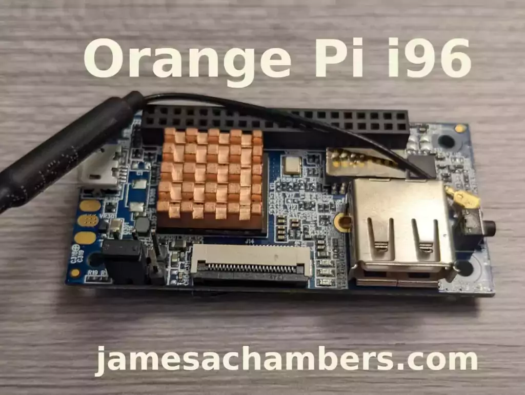
I recently got a Orange Pi i96 (thanks munecito!) and this board is very exciting because it was purchased on sale for ~$10! That is insanely cheap. The reason it’s so cheap is because it’s a headless board that doesn’t contain any display-out ports.
If you are going to be using the board headless anyway (I use most of my SBCs headlessly) you may be able to save a fortune with this board. Let’s get started!
Hardware Used
The Orange Pi i96 is a low-cost board from the Orange Pi line of SBCs. It uses the RDA8810 SoC and has 256MB LPDDR2 SDRAM. It’s well suited for headless tasks and is astonishingly cheap.
Links: Amazon.com*, AliExpress.com*, Amazon.ca*, Amazon.co.uk*, Amazon.de*, Amazon.es*, Amazon.fr*, Amazon.it*, Amazon.sg*

The Geekworm copper heatsink set is designed to fit many different single board computers. It uses thermal conductive adhesive which many “cheap” heatsink kits for SBCs don’t have. Eliminates hotspots and reduces throttling. Can be further enhanced by powered cooling over the heatsinks.
Links: Amazon.com*, Amazon.ca*, Amazon.co.jp*, Amazon.co.uk*, Amazon.de*, Amazon.es*, Amazon.fr*, Amazon.it*

The Orange Pi official mouse uses 2.4GHz wireless to give you a wireless mouse experience with the Orange Pi
Links: Amazon.com*, AliExpress*

The Orange Pi monitor is meant to be a portable monitor you can take anywhere. It has a resolution of 1080P and features a hinge in the back that folds out to support the monitor.
Links: Amazon.com*, AliExpress*
Getting Started
EDIT: I now recommend using my fixed Orange Pi i96 image as it will fix your USB port to be able to operate at full speed and give you a much newer OS of Debian Bullseye.
Alternatively you may use the official images (not recommended for this board). If you’d like to use the official images instead head to the official Orange Pi downloads page:
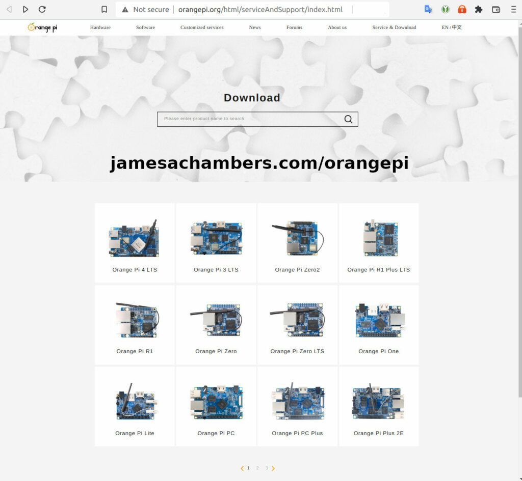
Now select the Orange Pi i96 from the list. I will be using Ubuntu Linux for this guide but you may use Armbian as well.
If you are wanting to try Android I highly recommend seeing my Orange Pi Android Installation Guide as the installation process is different than Linux.
Writing the Image
The images are typically distributed as a .tar.gz file. The name of the Ubuntu image tar.gz file at time of writing was OrangePi_i96_ubuntu_xenial_server_linux3.10.62_v0.0.4.tar.gz.
We will need to extract this file. If you are using Windows then grab 7-zip to be able to extract a .tar.gz file.
Inside this file will be a .img file. Since I downloaded the Ubuntu image the name of my file was OrangePi_i96_ubuntu_xenial_server_linux3.10.62_v0.0.4.img. This is the image that we are going to write to our SD card.
There are several choices to write the image to your SD card. If you are on Windows I recommend Win32DiskImager. Etcher is also available for Windows/Linux/Mac OS X.
Write the image to the SD card using your preferred software.
First Startup
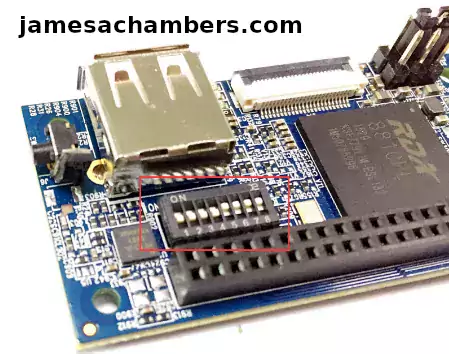
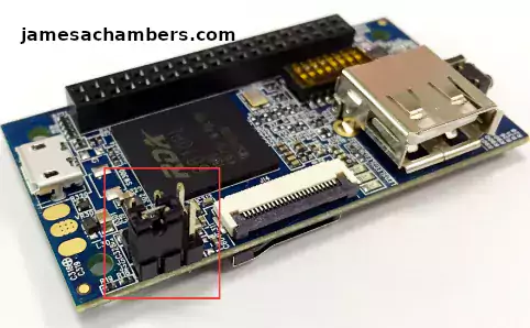
Before starting up you should make sure that the Orange Pi’s switches are in these positions (indicating to boot from SD card):
We’re ready to put the SD card into the Orange Pi i96. But how are we going to connect to the device? There’s no network port and the device isn’t configured to connect to our WiFi yet.
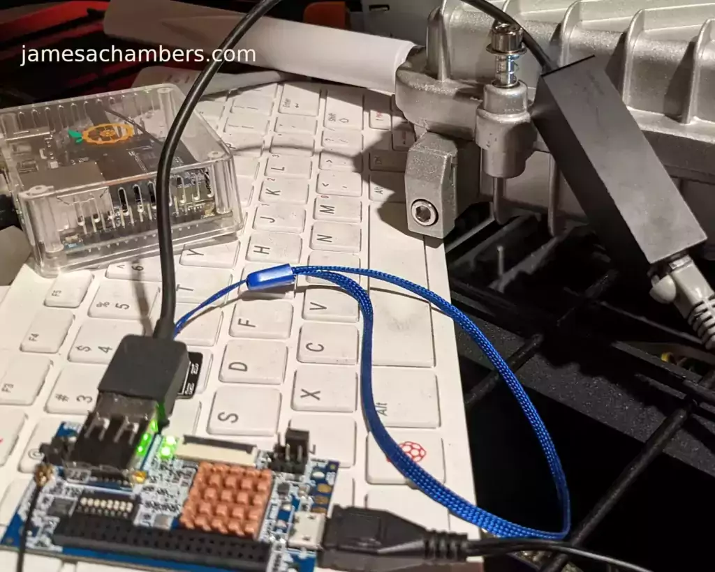
Connection Option #1
If you happen to have a USB to Ethernet adapter that is the easiest way to connect to the device for initial configuration:
Connection Option #2
If you have a TTL to USB serial debug adapter* you can use that as well. See the OrangePi instructions for that method.
Initial Configuration
orangepi-config Utility
Once you’ve connected it’s time to do some basic configuration. We will use the tool orangepi-config:
sudo orangepi-config
You may now set the WiFi settings, etc. The orangepi-config is just like raspi-config if you’ve ever used that on a Raspberry Pi.
Don’t reboot before doing the next section.
Fix Second Startup (Debian / Ubuntu)
You will notice if you reboot the device it will often not come up the second startup. This is especially likely if you performed a sudo apt dist-upgrade.
To prevent this I recommend removing the alsautils package. This will impact sound functionality on the board but as I was not using it and intended to use this more as a headless board this was fine for me.
sudo apt purge alsa-utils
If you need to have the sound working on the board there is an alternate solution available here.
This is not necessary in my Legendary image as it has kernel fixes for these issues (highly recommended)
Set Timezone
Replace my timezone with yours in the following commands:
rm /etc/localtime
ln -s /usr/share/zoneinfo/America/Denver /etc/localtime
Setup Locales
Setting the locales isn’t in orangepi-config (such as it is in raspi-config) but here’s a quick way to set them:
sudo apt install locales -y
sudo dpkg-reconfigure locales
Setup Wireless CRDA Regulatory Domain
For the wireless to function very well at all you need to set the wireless regulatory domain.
If you are not using my image then you will first need to install the crda package with:
sudo apt install crda -y
Now we can set the regulatory domain by editing the following file:
sudo nano /etc/default/crda
At the bottom of the file there is this line:
REGDOMAIN=
Put the 2 letter country code for your country. Mine is “US”. Once finished press Ctrl+X then Y to save the file.
Optional – Upgrade Debian OS to Buster/Bullseye
Note that this will not upgrade the kernel. You can upgrade everything else though including all the way up to Bullseye. You should do this one release at a time and start with “Stretch” and then do “Bullseye” afterward.
If you are using the Debian installation you can upgrade to Buster by editing your /etc/apt/sources.list file.
Change all instances of “stretch” in the file to “buster” and then do the following:
sudo apt update && sudo apt dist-upgrade -y
Once this has completed reboot the system (make sure you’ve done my fix second reboot section first by purging alsa-utils). Verify you are on Buster with
cat /etc/os-releasefor example:
root@orangepii96:/# cat /etc/os-release
PRETTY_NAME="Debian GNU/Linux 10 (buster)"
NAME="Debian GNU/Linux"
VERSION_ID="10"
VERSION="10 (buster)"
VERSION_CODENAME=buster
ID=debian
HOME_URL="https://www.debian.org/"
SUPPORT_URL="https://www.debian.org/support"
BUG_REPORT_URL="https://bugs.debian.org/"
Now you can upgrade to Bullseye. It’s almost the same as upgrading from Stretch to Buster but there has been a change in the security updates server format. Here is a working “Bullseye” apt sources file for the Debian Orange Pi i96 image:
root@orangepii96:/# cat /etc/apt/sources.list
deb http://ftp.debian.org/debian bullseye main contrib non-free
#deb-src http://ftp2.cn.debian.org/debian bullseye main contrib non-free
deb http://ftp.debian.org/debian bullseye-updates main contrib non-free
#deb-src http://ftp2.cn.debian.org/debian bullseye-updates main contrib non-free

deb http://security.debian.org/ bullseye-security main contrib non-free
#deb-src http://security.debian.org/ bullseye-security main contrib non-free
Once you’ve changed the files do a sudo apt update and make sure you don’t see any errors. If everything looks okay start the Bullseye upgrade with:
sudo apt full-upgrade -yAfter a reboot you should be on Bullseye! We can verify this with cat /etc/os-release:
orangepi@orangepii96:~$ cat /etc/os-release
PRETTY_NAME="Debian GNU/Linux 11 (bullseye)"
NAME="Debian GNU/Linux"
VERSION_ID="11"
VERSION="11 (bullseye)"
VERSION_CODENAME=bullseye
ID=debian
HOME_URL="https://www.debian.org/"
SUPPORT_URL="https://www.debian.org/support"
BUG_REPORT_URL="https://bugs.debian.org/"
orangepi@orangepii96:~$ uname -a
Linux orangepii96 3.10.62-rel5.0.2+ #4 PREEMPT Wed Mar 18 18:49:25 CST 2020 armv7l GNU/Linux
Notice that the kernel has not changed at all (as cautioned at the beginning of the section) but everything else on the system will be Bullseye!
Performance Benchmarking
I benchmarked the board using a SanDisk Extreme SD card on my Pi Benchmarks web site. This gives us comparable results between boards and there are over 30,000 benchmarks submitted for various boards / storage devices.
I had a total score of 497. This was below average or off from an average Raspberry Pi setup by about 47%.
To be clear the storage performance on the board is relatively low compared to the Orange Pi Zero 2 or a Raspberry Pi (Zero or 4). That is to be expected for a price of around ~$7-$10.
I’m not sure I would say this is a disappointing result though. We are talking about a board that is a single digit number of dollars. For the price point that is fantastic performance! In fact for the price point it’s a wonder that it works at all.
Conclusion
It’s a great board. At a price point of $7-$10 it reminds me of the really, really old Raspberry Pi Zero days where you could actually get a Raspberry Pi for around that price point.
The Zero 2 is a significantly more powerful board. It benchmarked much higher than the i96 but it also costs significantly more. If you need more power that board will be a better choice. If you’ve never had an Orange Pi before I would recommend the Zero 2 first as this board is quite a bit trickier and has more outdated software available for it.
The version of Ubuntu on this board is also quite old (Ubuntu 16.04 / Xenial) compared to the Orange Pi Zero 2 which is actually running a modern 5.X kernel whereas this one is a 3.X kernel. Make sure that is not going to be a problem or you will want to step up to a higher Orange Pi. The i96 is definitely meant for simple services / projects that don’t need a lot of power. It’s perfect for those.
If you need a headless board then the Orange Pi i96 may very well fit the bill for you, the price is certainly right! Don’t skip the heatsinks though. It got very warm during testing (warm enough to freeze once during consecutive benchmarks) and Orange Pis are known to get quite hot!
Other Resources
I highly recommend using the Legendary i96 Debian Bullseye image available here
I’ve also reviewed the Orange Pi portable monitor here
Don’t miss my Orange Pi Zero 2 Review / Tips / Guide for another great board (with display connections)
I’ve also reviewed the Orange Pi 3 LTS which is roughly equivalent in power to a 2GB Pi 4
If you’re trying to set up Android definitely see my Orange Pi Android Installation Guide
For the fastest storage options check out my Linux storage benchmarking script


howto attach nand as extra space:
bootargs:mtdparts=rda_nand:-(extra_space) ubi.mtd=0
this basically repartitions the nand, without changing the kernel
boot into it, and execute the following commands:
ubiformat /dev/mtd0 # formats the whole nandubimkvol /dev/ubi0 -N extra -m # creates an ubivol with the name extra
mount -t ubifs ubi0:extra /extra # mount it on /extra
if you want to do this via fstab, add the following entry to /etc/fstab
ubi0:extra /extra ubifsthats it, enjoy 🙂
Hey Marco,
That’s a great guide for the NAND storage! I’d be willing to configure this by default perhaps except I still worry about if people are using their NAND partitions in other ways. This is probably the best guide for now to utilize this space!
I wonder if we could just put some utility scripts in the home folder related to NAND potentially. There are already some scripts like this although they are mostly applicable to the 2G (and should honestly probably just be removed). There’s also a “CameraTest” folder and test_playback.sh. Maybe something like a ./setup_nand.sh script that just has a warning that anything on there will be removed and then it could potentially set up the /etc/fstab entry (and possibly add the bootargs if this is possible within the OS, I know there are some utility scripts out there to directly write to the NAND and that might be necessary to modify the bootargs).
I’m definitely open to any ideas on how to safely integrate this into the image (and we could add any necessary documentation on how to use it to the README) and would be more than willing to do so!
Hi James,
I have a version of libwiringpi for the i96.
Let me know if you can compile it and add it to the rootfs.
MehdiZAABAR/WiringPi
Regards.
Hey MZA,
Great work! I was able to build the utility on my i96 and am building v1.12 with this installed. This will replace the gpio tool I have installed (which is a copy of opio) and replace it with the proper WiringPi GPIO utility.
Patb’s utility will still be available as opio as well but I really like having the WiringPi library in here as it’s the one that is covered in the Orange Pi documentation and seems like the intended tool to use. Thanks for doing this MZA, V1.12 should drop shortly with this utility preinstalled!
I also left the source code for the utility in the home folder (/root/WiringPi). This will make it end up just like the Orange Pi documentation (where they download the broken version of WiringPi and build it and install it) only your version actually works!
Great James.
I’m back to my SPI screen now that the GPIO are more or less working with the wiringPi( not all of them, there still some pins that do not output HIGH on the header when set to 1, but its the same behavior with opio, may be a schematic error ?).
My screen remains dead with two test applications, I think that the spidev3.0 does not work, I’ll update my image to your latest then dig around the spi declaration you’ve added to the kernel or maybe try to work with another SPI port.
Hey MZA,
Great findings! Yes, that is exactly what I would suggest to do. I think spidev is assigned to bus / interface 3 (which is why it’s spidev3:0).
The file you would use to configure this is kernel/arch/arm/mach-rda/devices.c. This file is in my project meant to be copied over the top of the produced OrangePiRDA folder. On line 274 there is this platform data definition:
static struct spi_gpio_platform_data spi_gpio_data = {.sck = 2, // spi pins on the comb
.mosi = 4,
.miso = 3,
.num_chipselect = 1, // this is the number of devices (we will only connect the screen, but can be extended for spidev)
};
struct platform_device rda_spi_gpio = {

.name = "spi_gpio", // spi driver name

.id = 3, // bus number, because spi0 spi1 spi2 is already described in this file, then this one will be 3

.dev = {

.platform_data = &spi_gpio_data,

}};
Look at all those pin configurations. Remember that the person who wrote these changes was using the i96 2G. Are the pin assignments in this file right for the i96? It sure doesn’t sound like it but it might be problems in other parts of the driver/controller.
On line 1585 of devices.c:
.modalias = "spidev", // driver name.max_speed_hz = 32000000,
.mode = SPI_MODE_0,
.bus_num = 3, // our spi number is 3
.chip_select = 0,
.controller_data = (void *) 5, // CS pin
},
Here are again more pin assignments that are based off his work on the i96 2G. I have zero doubt that you have a much, much better understanding of what the correct pin assignments and all of that should be. I can definitely at least tell you exactly where to go though and those are the places you would want to take a look at / start experimenting with for sure.
The WiringPi issue is interesting as well. It’s very possible that patb has a weird correction/fix in the opio source code for this as I remember when reading his documentation he did mention there were some oddities like that. My build system for this project actually clones your project from GitHub (from scratch each build) so it will update itself as I produce new builds. In other words if you fix/change anything in your WiringPi repository those changes will automatically go into the next build/release. If you ever have any changes like this worth pushing out just drop me a comment and I will generate a new release.
Let me know what you find!
Yes nice.
Ok, let’s start, pin assignment seems not correct, mosi should be SPI2_DIO which is on RDA pin 3, miso is pin 4.
On the I96 header, only SPI2_CS1 is available, so if only spidev3.0 is available, pin assignment (.controller_data) should be pin 6.
I’ll rebuild the kernel and give it a try.
Now, second point is, if spi_gpio is the driver to use for spi communication, then pins should be assigned to GPIO not to SPI2, this is not what I see : opio and gpio tools display the alternative function to the related pins. I’ll try for force the io mux to set them back to gpio but we should consider working the native rda spi driver.
My Best.
I confirm from the first static tests, the pins MOSI and MISO were inverted.
My test was to wire a GPIO ( A28, Header 32) out to SPI2_DI ( A4 H10) => what ever value output by the GPIO, spidev_test received 00. After kernel update, spidev_test reads the GPIO value.
Now, my screen is still dead, I’ll check the CS pin mode.
Chip select remains desperately low, ( it shows 2mV when spidev_test runs with a very low speed and a big frame to transfer). A physical loop on the SPI2_DIO to SPI2_DI does not bring neither the DEADBEEF.
Driver Loop mode ( #spidev_test –loop ) is not supported by the spidev driver, to my surprise. It displays spidev spi3.0: setup: unsupported mode bits 20, can’t set spi mode: Invalid argument. Any hint ?
Hey MZA,
Very interesting findings so far! So from what I can tell it seems to be missing support for loop modes. The closest thing I’ve really found so far is this.
Yes I have never seen anything in the code related to SPI_LOOP. This cannot even be set via device tree which means that this would all have to be done/supported in the devices.c file I think (or possibly even another driver but my guess is devices.c is the key). I doubt this functionality is present in the driver at the moment.
It doesn’t even look like the Raspberry Pi used to support this (as this is one of 2 or 3 results I get when I quote “unsupported mode bits 20”. Maybe it does now (there’s almost certainly a bunch of overlays for it on the modern Pi) but it didn’t when the Orange Pi i96 was released it doesn’t look like. My guess is this is correct without further modifications / additions to the driver!
It does not matter the loop is not supported, this just provides an answer to a previous comment on testing spi loop that fails with spidev_test.
I used a physical loop and it does not read the “DEADBEEF” string, although it can read a GPIO output. This means RX works but TX does not. ( weird huh ?)
Now what disturbs me is that the rda_spi nodes are not created after boot and that in the rda_spi_board_info table ( where you inserted the spidev driver) they are not listed. I’m still on this topic. May be SPI would work with the native rda_spi drivers if we register them properly and create the device nodes in /dev.
This line in spi-rda.c makes sens with the spidev_test LOOP problem
/* the spi->mode bits understood by this driver: */master->mode_bits = SPI_CPOL | SPI_CPHA | SPI_CS_HIGH;
Hey MZA,
That looks promising. Can you add the capability there with
| SPI_LOOPappended? That’s definitely exactly what I would try and what I was getting at with linking to that post. There’s only 3 hits on Google for your quoted error at all and most of them say it’s missing capabilities. I guess it’s just a question of whether it will build with that capability without errors. I added no such capabilities of any kind to the controller and only the linked changes that person added (which was not instructions on how to enable spidev, he only said it could be and that this is where we would add it). Who knows what other capabilities it may be missing as his changes were not intended to add spidev so there may be several things like this missing.Great work on this. I think you’ve got to be very close. I definitely think the native SPI could be mapped and used in here as well. The spidev device didn’t exist at all until we added it. You can look at the original code for a comparison but there was nothing like that device at all. It was added completely out of thin air. Of course that means there’s a lot of low level stuff (such as exactly the right pin assignments) that needs to be in place for it to work but I really think you’re close here!
I got the device nodes created, I have changed the devices declaration.
ex:
RDA_SPI_PARAMETERS spi2_controller_data = {.inputEn = true,
.clkDelay = RDA_SPI_HALF_CLK_PERIOD_0,
.doDelay = RDA_SPI_HALF_CLK_PERIOD_0,
.diDelay = RDA_SPI_HALF_CLK_PERIOD_1,
.csDelay = RDA_SPI_HALF_CLK_PERIOD_1,
.csPulse = RDA_SPI_HALF_CLK_PERIOD_0,
.frameSize = 8,
.oeRatio = 8,
.rxTrigger = RDA_SPI_RX_TRIGGER_4_BYTE,
.txTrigger = RDA_SPI_TX_TRIGGER_1_EMPTY,
};
static struct spi_board_info rda_spi_board_info[] = {
#ifdef CONFIG_FB_RDA_DPI
{
.modalias = RDA_DPI_PANEL_DRV_NAME,
.max_speed_hz = 500000,
.bus_num = 0,
.chip_select = 0,
//.controller_data =
},
#endif
{
.modalias = "tlv320aic23-spi",
.max_speed_hz = 1000000,
.bus_num = 0,
.chip_select = 1,
.controller_data = (void *)&tlv320aic23_spi,
},
{
.modalias = "spidev", // driver name
.max_speed_hz = 20000000,
.mode = SPI_MODE_0,
.bus_num = 1,
.chip_select = 0,
.controller_data = (void *) &spi1_controller_data,
},
{
.modalias = "spidev", // driver name
.max_speed_hz = 20000000,
.mode = SPI_MODE_0,
.bus_num = 1,
.chip_select = 1,
.controller_data = (void *) &spi1_controller_data,
},
{
.modalias = "spidev", // driver name
.max_speed_hz = 20000000,
.mode = SPI_MODE_0,
.bus_num = 1,
.chip_select = 2,
.controller_data = (void *) &spi1_controller_data,
},
{
.modalias = "spidev", // driver name
.max_speed_hz = 10000000,
.mode = SPI_MODE_0,
.bus_num = 2,
.chip_select = 0,
.controller_data = (void *) &spi2_controller_data,
},
{
.modalias = "spidev", // driver name
.max_speed_hz = 10000000,
.mode = SPI_MODE_0,
.bus_num = 2,
.chip_select = 1,
.controller_data = (void *) &spi2_controller_data,
},
};
Now, the spidev_test transfer is executed but I have strange behavior, I see the txed frame in the rx.
There is a note in the rda-spi controller driver that says ” This is a DMA-only driver.” but when RDA SPI DMA flag is enabled, there are unstoppable warning flags about the master having already the ddr. I disabled it.
In both cases, with or without DMA, I have the same rx result with spidev_test. It seems worse than before, at least I was reading the gpio output when using a physical loop ( SPI2_DIO to A28), now no more.
RXed frame00 00 00 00 00 00
00 00 00 00 00 00
00 00 00 00 FF FF
FF FF FF FF FF FF
FF FF DE AD BE EF
BA AD F0 0D FF FF
FF FF
when Txed frame is
0xFF, 0xFF,0x40, 0x00, 0x00, 0x00, 0x00, 0x95,
0xFF, 0xFF, 0xFF, 0xFF, 0xFF, 0xFF,
0xFF, 0xFF, 0xFF, 0xFF, 0xFF, 0xFF,
0xFF, 0xFF, 0xFF, 0xFF, 0xFF, 0xFF,
0xDE, 0xAD, 0xBE, 0xEF, 0xBA, 0xAD,
0xF0, 0x0D, 0xFF, 0xFF, 0xFF, 0xFF,
Hey MZA,
That is very interesting. I’ve seen some of the references to DMA throughout the code and I even tried enabling one of these once while testing and got the same errors while building.
Did you change the bus num to 2 in the platform definition data to match? I never was able to get it to work on bus num 2. The closest it seemed to get was on bus num 3. That would be this:
struct platform_device rda_spi_gpio = {
.name = "spi_gpio", // spi driver name
.id = 3, // bus number, because spi0 spi1 spi2 is already described in this file, then this one will be 3
.dev = {
.platform_data = &spi_gpio_data,
}};
Did you change the id here to match?
Hi,
I’ve got the spi-gpio driver work with only gpio pins, it was hard but now I can go back to what was failing and have fixes. I’ll post my devices.c file through github.
I suppose that spi-gpio did not work on the previous trials because pins were not assigned to gpio function. We used the spi2 pins and we did not set them manually to gpio function. the driver did not do it either.
The rda-spi driver ( native spi driver) did not work and that is another problem that should be debugged.
Hey MZA,
Great findings, and fantastic work! That makes perfect sense that some of the pin assignments were wrong. I definitely figured you would be the best person to diagnose these (and definitely better than myself).
I’ll watch for whatever you submit and get the changes in for sure. Great work on this MZA!
Hey again, i created a telegram group where we can write instantly and share opinions and progress about anything i96 related.
Everyone is welcome, but mostly devs are needed to get it running.
I have another idea which could be interesting in general.
Since we are powering the i96 over the OTG-port, couldnt we somehow integrate a serial connection over it?
This would be nice because it would allow us to do the initial programming (or when something fails) directly by connecting it to a pc/laptop or whatever you prefer.
Hey Marco,
I believe this specific feature was added yesterday. The i96 can be used as a USB serial console as of 1.11 I believe (or at least all the kernel flags are enabled for it now)!
I cant get it to work, i guess its because musb on the otg port is not set to host, cant figure it out
i can see this happening in dmesg
root@orangepi:~# dmesg | grep usb[ 0.374511] v_usb: 1800 2800 mV normal standby
[ 0.397766] usbcore: registered new interface driver usbfs
[ 0.398376] usbcore: registered new interface driver hub
[ 0.399047] usbcore: registered new device driver usb
[ 0.704589] usbcore: registered new interface driver usb-storage
[ 0.706542] platform disable musb
[ 0.706787] musb-hdrc: ConfigData=0x1a (UTMI-8, HB-ISO Rx, HB-ISO Tx, SoftConn)
[ 0.707763] musb-hdrc: HDRC RTL version 2.0
[ 0.708312] gpio-vbus gpio-vbus: registered host 'musb-hdrc'
[ 0.808837] usbcore: registered new interface driver usbmouse
[ 0.903564] musb_gadget_pullup android usb didn't ready
[ 0.905395] android_usb gadget: Mass Storage Function, version: 2009/09/11
[ 0.906066] android_usb gadget: Number of LUNs=1
[ 0.907592] android_usb gadget: android_usb ready
[ 0.908020] gpio-vbus gpio-vbus: registered gadget 'musb-hdrc'
[ 0.908752] musb-hdrc musb-hdrc: MUSB HDRC host driver
[ 0.909423] musb-hdrc musb-hdrc: new USB bus registered, assigned bus number 1
[ 0.911560] platform enable musb
[ 4.898315] usb cable connect...
[ 6.714355] usb cable disconnect...
usb cable disconnect? huh
Hey Marco,
I don’t think you can do what you’re trying to do without a powered USB hub or special splitter (even with a phone). Look at this: USB OTG cables that support charging.
Do you have something like that? If not I would not expect this to work and it won’t work with a phone either (at least one without USB-C but more on that in a moment). They get more and more complicated the further down you go but I’m pretty sure this is completely normal. It’s not as easy as powering it and having a USB serial console over the same cable without having a more complicated adapter setup I don’t think.
Maybe this is fixed with USB-C? I’m positive USB-C gives you ways to do this without a janky adapter and USB-C was pretty much born to get rid of problems like this (USB-C supports USB-PD or power delivery but micro does not in the same way). The Orange Pi i96 doesn’t have USB-C though so I’m pretty sure this era of articles/tech is right to do this for this type of device. It’s exactly from when the i96 was originally released at least. It wouldn’t be as much problem on a phone though unless you wanted to charge it at the same time. That is the problem though. The Orange Pi i96 doesn’t really have a battery that we can just use the serial console and run off battery power and not have to deal with the adapter.
It definitely ties into the theme we’ve been running into of if this board wasn’t basically abandoned then we’d likely already have a i96 V2.0 (not 2G, a newer version of this board that was never made) and that would undoubtedly have USB-C. My Orange Pi Zero 2 has USB-C and is powered through it and would not have this problem for example due to the newer USB-C technology stack. Of course if they did this then the board likely would not cost $6-7 and would cost about 4x-5x that. Other Raspberry Pi Zero knockoffs like the Radxa Zero cost many, many times what the i96 does but they would have USB-C.
That Radxa board is exactly what you would want to do this (and has a quad core processor). It’s all USB-C basically on that one! It’s also exactly what I would expect the i96 2 to look like if it was ever made. It looks like you can get it for as low as $28 although it’s hard to find someone who is stocking one that cheap as they have different levels of RAM and eMMC storage built in on the Radxa boards. Definitely still much cheaper than getting a Pi Zero or Pi Zero 2 and honestly that Radxa’s quad core processor probably outclasses the Zero 100% for sure and possibly the Zero 2 as well. I have a Pi Zero 2 waiting to be picked up at the post office (I bought a scalped one from Europe for about $55) so I will test how powerful the Raspberry Pi Zero 2’s processor is for the absurd price you’d have to pay to actually get your hands on one.
well, the i96 has a battery input port, ill try to use some of my 18650 cells and see if it will power from that and if the otg port is usable then
Hey Marco,
That should definitely do it but I’m looking at some other kernel options and I don’t see:
# CONFIG_USB_G_SERIAL is not setI do see:
CONFIG_USB_F_ACM=yMake sure you are doing:
modprobe g_serialI believe for gadget mode serial. It won’t configure itself most likely as it’s also configured as an Android gadget device and there are several other drivers in there as well. This won’t be plug and play unless I remove the other drivers like the android_usb one. I literally have no idea what the android gadget even does. A lot of other projects remove it (almost all of them that got far enough to be worrying about things like that).
It might need more kernel options enabled too. I didn’t attempt to do this as this was a pull request for someone else. They didn’t tell me exactly how they were doing it. They might be connecting a USB cable to the regular USB port for all I know for their USB serial support so we’ll have to see what you find!
modprobe g_serial wont be working because the module doesnt exist
Hey Marco,
That’s going to be a problem. Let me see what I can do real quick here!
pi is working from a 18650 cell, these are the messages i get rn:
[ 0.374511] v_usb: 1800 2800 mV normal standby[ 0.397705] usbcore: registered new interface driver usbfs
[ 0.398315] usbcore: registered new interface driver hub
[ 0.399047] usbcore: registered new device driver usb
[ 0.703613] usbcore: registered new interface driver usb-storage
[ 0.705505] platform disable musb
[ 0.705749] musb-hdrc: ConfigData=0x1a (UTMI-8, HB-ISO Rx, HB-ISO Tx, SoftConn)
[ 0.706665] musb-hdrc: HDRC RTL version 2.0
[ 0.707336] gpio-vbus gpio-vbus: registered host 'musb-hdrc'
[ 0.808776] usbcore: registered new interface driver usbmouse
[ 0.903625] musb_gadget_pullup android usb didn't ready
[ 0.905456] android_usb gadget: Mass Storage Function, version: 2009/09/11
[ 0.906127] android_usb gadget: Number of LUNs=1
[ 0.907653] android_usb gadget: android_usb ready
[ 0.908020] gpio-vbus gpio-vbus: registered gadget 'musb-hdrc'
[ 0.908752] musb-hdrc musb-hdrc: MUSB HDRC host driver
[ 0.909423] musb-hdrc musb-hdrc: new USB bus registered, assigned bus number 1
[ 0.911560] platform enable musb
[ 6.779724] musb-hdrc musb-hdrc: VBUS_ERROR in a_wait_bcon (80, <SessEnd), retry #1, port1 00000100
[ 7.745727] musb-hdrc musb-hdrc: configured as A device timeout
[ 7.869689] musb-hdrc musb-hdrc: VBUS_ERROR in a_wait_bcon (80, <SessEnd), retry #2, port1 00000100
[ 8.845275] musb-hdrc musb-hdrc: configured as host timeout
[ 9.919677] musb-hdrc musb-hdrc: VBUS_ERROR in a_wait_bcon (80, <SessEnd), retry #3, port1 00000100
[ 10.878601] musb-hdrc musb-hdrc: configured as host timeout
[ 11.959960] musb-hdrc musb-hdrc: VBUS_ERROR in a_wait_bcon (80, <SessEnd), retry #3, port1 00080108
root@orangepi:/sys/class/android_usb/android0# cat state

DISCONNECTED
i cant get it to work via android_usb either, seems that otg is somehow not in host mode?
too bad for now
Hey Marco,
Did you configure it?
root@orangepii96:/sys/class/android_usb/android0# lsbDeviceClass bcdDevice f_acm f_charge_only f_mtp functions iSerial power uevent
bDeviceProtocol enable f_adb f_ffs f_ptp iManufacturer idProduct state
bDeviceSubClass f_accessory f_audio_source f_mass_storage f_rndis iProduct idVendor subsystem
root@orangepii96:/sys/class/android_usb/android0# cat *
0
0
0
ffff
0
cat: f_accessory: Is a directory
cat: f_acm: Is a directory
cat: f_adb: Is a directory
cat: f_audio_source: Is a directory
cat: f_charge_only: Is a directory
cat: f_ffs: Is a directory
cat: f_mass_storage: Is a directory
cat: f_mtp: Is a directory
cat: f_ptp: Is a directory
cat: f_rndis: Is a directory
AndroidAndroid0123456789ABCDEF0001
18d1
cat: power: Is a directory
DISCONNECTED
cat: subsystem: Is a directory
It says it’s not even enabled. So no it’s definitely not in host mode. See this link.
To put it in host mode you would set the parameters for how you want the USB gadget to identify itself (or just leave them default to test) and then do:
echo 1 > sys/devices/virtual/android_usb/android0/enableYou also need to set the functions you want to use. If you want to set the function for serial you would add “serial” to the functions string. This definitely won’t just work though. I’ve never used this type of device before but it doesn’t look too hard to do here from the examples.
cat sys/devices/virtual/android_usb/android0/functionsis completely empty. That means it’s working exactly the way it should (it’s configured to do nothing basically by default, whether that was intentional or this is broken/unfinished functionality is anyone’s guess but I’d be surprised if it doesn’t work once you configure it).In other words it looks like by default this is broken/unconfigured just like so many other things in the base image such as the WiFi regulatory country, anything to do with SPI and GPIO, and a bunch of other things that once you configure them will work normally. That’s because Orange Pi didn’t write that code (the code is probably fine). They just failed to implement almost anything correctly at all in their base image basically so we have to configure it for them here. I have no doubt the driver itself and the hardware is fine and that Orange Pi failed to implement support for it correctly in their image/configuration basically (or didn’t even realize that there was a software/image configuration component to all these features they were promising on the board, it really makes you wonder sometimes looking at some of the missing things in the image).
i did everything you can imagine according to the usual manuals
i put for example rndis in functions, put some iProduct idVendor and set it to enable,
nothing happens. for example:
root@orangepi:/sys/class/android_usb/android0# lsbDeviceClass bcdDevice f_acm f_charge_only f_mtp functions iSerial power uevent
bDeviceProtocol enable f_adb f_ffs f_ptp iManufacturer idProduct state
bDeviceSubClass f_accessory f_audio_source f_mass_storage f_rndis iProduct idVendor subsystem
root@orangepi:/sys/class/android_usb/android0# cat idProduct idVendor
0001
18d1
root@orangepi:/sys/class/android_usb/android0# lsusb
Bus 001 Device 001: ID 1d6b:0002 Linux Foundation 2.0 root hub
root@orangepi:/sys/class/android_usb/android0# echo rndis > /sys/class/android_usb/android0/functions
root@orangepi:/sys/class/android_usb/android0# echo 1 > /sys/class/android_usb/android0/enable
root@orangepi:/sys/class/android_usb/android0# ip link set rndis0 up
dmesg result is
[ 349.881469] rndis_function_bind_config MAC: 00:00:00:00:00:00
[ 349.882141] android_usb gadget: using random self ethernet address
[ 349.882812] android_usb gadget: using random host ethernet address
[ 349.904052] rndis0: MAC ba:9d:23:2d:6f:9c
[ 349.904357] rndis0: HOST MAC 8e:a7:0b:00:4f:41
[ 353.588073] rndis0: eth_open
[ 353.590881] IPv6: ADDRCONF(NETDEV_UP): rndis0: link is not ready
but still:
root@orangepi:/sys/class/android_usb/android0# cat stateDISCONNECTED
whats more curious is, when i power the i96 over battery, the normal usb port is not available anymore, devices not getting recognized.
so its a total failure.
also via the lsusb command you can see that the otg port is set as HOST, so i could propably attach a usb device on the otg port, but its sad that the normal usb port dont work anymore
but when i let the otg cable connected to power instead and boot the pi up, the usb port works normally tho….
so this seems to be a complete clusterfuck, the whole driverbase is most or less useless and has to be refactured and reprogrammed
I agree with this. There is not a good explanation for what you’re seeing here other than the driver is broken / needs fixes. Probably a *lot* of fixes. I feel like even when the driver wasn’t configured you shouldn’t have been getting the VBUS_ERRORs. It should have just done nothing or the activity would have just probably looked like a regular disconnect again / not an error.
Thank you for investigating this functionality anyway. I will definitely put on my list that I need to get myself a battery set up to connect to this device so I can do some of this testing you have done as well!
I’m curious what the person who did the pull request (that was Steve) adding the kernel configuration parameters for USB serial was doing. Perhaps they were connecting it via the main USB-A port and using it a completely different way.
Hi – the serial driver I needed was out of the USB-A to a 3D printer control that uses a CH340 chip (goes from USB to TX/RX). The PR did not have anything to do with the OTG functions.
Hey Steve,
Thanks for clarifying! I suspected as I examined your flags more closely as none of them were OTG so this makes sense for sure. The OTG driver has many known issues as one of my original fixes implemented in this image was fixing the USB to not be stuck to “Full Speed” mode. It was supposed to support this but just didn’t with the original driver. I’d imagine the driver needs fixes for this functionality to work judging by some of the nasty dmesg errors!
Hey Marco,
That is very curious. I wonder if some of my backup RAID hardware battery packs have the same connector as the Orange Pi wants that I could recreate what you are doing here. I will have to check!
This does sound like something more is going on. The other USB port disappearing on functionality does sound like some kind of low level driver/bug.
The other post you posted that had the VBUS_ERRORs is curious too. I think you’re right and that something is breaking here on battery. I definitely can’t explain the other port not functioning. That sounds super wrong / like a bug to me!
i digged a little bit into the config, and i found a variable called:
CONFIG_USB_RDA_OTG
the result is followed by:drivers/usb/musb/rda.c: In function ‘rda_start_host’:
drivers/usb/musb/rda.c:136:5: warning: unused variable ‘power’ [-Wunused-variable]
CC net/ipv6/xfrm6_mode_beet.o
LD drivers/usb/musb/musb_hdrc.o
LD drivers/usb/musb/built-in.o
make[3]: *** No rule to make target 'drivers/usb/otg/rda_otg.o', needed by 'drivers/usb/otg/built-in.o'. Stop.
make[3]: *** Waiting for unfinished jobs....
CC drivers/usb/otg/otg.o
so there basically was the idea behind it, to switch the otg port from host to client mode, which is exactly what i need, but it seems that it is not programmed…
shush….
so i looked more into it and this is kind of funny:
we found out that when the OTG port is not plugged in, the usb port is not working anymore because musb-hdrc doesnt work anymore, who knows why this is bound to the otg port.
anyway, the musb-hdrc is ONLY working for the usb-port and not for the OTG port, so whenever i change something in the rda.c, this only affects the main usb port and not the OTG port.
however /sys/devices/platform/musb-rda.0/musb-hdrc/udc/musb-hdrc/is_otg is 1, so i think that the otg port is forced into udc mode already, but now iam stuck, iam not a linux kernel/module dev
there are already some people in the telegram group, but we need more 😀
Hey Marco,
I think it’s going to be pretty complicated to fix. The android_usb stuff is hard coded into the musb driver itself. When I try to disable the android USB mode it actually won’t build the kernel because the driver is hardcoded to initialize and use that device (even though it’s broken). That was just from turning their flag off to build the android_usb driver and it completely broke it and won’t build without it. I’d probably have to go in and delete all references to it from the rest of the drivers.
I’d imagine you’re running into the same thing. The drivers have hardcoded references to some of those parts provided in the kernel flags. You should be able to turn it off like you are without errors (unless there’s a bunch of codependencies). I’m not surprised it won’t build without it though as there is a *lot* of improper code in the drivers that makes turning these flags off/on actually stop the kernel from building at all (not how it’s supposed to work).
I’m definitely not the guy to do this one myself probably as I don’t really have a use case that I would subject myself to rewriting that driver (something that would take me at least dozens of hours for sure or maybe more, but the right person might be able to do in an hour or two). We probably need the right person who needs to use it to come along and do it (and if they have experience rewriting some of those lower level drivers all the better!).
I would hate myself for doing it afterward too since I know I will never use this functionality personally and that most of what I learn is going to be proprietary RDA knowledge/driver knowledge that is largely no longer relevant due to improvements in the Linux driver model, device trees and a bunch of other things that can be found on modern boards/Linux. That’s a super tough sell when not only do I get no money out of it but the knowledge isn’t even particularly useful for anything except this board and it will be extremely, extremely hard for me to figure it all out since I’m starting with basically nothing / no experience with that level of driver/board development.
The promise of useful knowledge is usually enough for me even without getting any type of pay or anything like that because the knowledge itself has a lot of value. In this case though it’s hard to see that value as we are talking about an obsolete board (relatively speaking, that doesn’t mean it doesn’t still have it’s uses especially for $6-$7) and kernel and things literally don’t work the same way on newer ones anymore. I think becoming a driver expert on this board doesn’t make a lot of sense and that it probably makes more sense to have someone who comes from that era and is already comfortable with it to jump in and clean this one up.
I’m not sure what it would cost to hire an engineer to do what you’re asking. Probably thousands and thousands of dollars even just for this single fix for the type of skills/knowledge required to be totally comfortable just going in and completely rewriting these! Like I said this would take the right person an hour or two to do if they are familiar with RDA chips and writing low level drivers (and are able to make sense of the spec sheets which have some issues/mistakes on them). This has already happened with some other fixes out there though so I’m not saying this is impossible or unlikely. There are people who have these skills and are willing to share them. We need one of those people for this fix though I think to happen most likely. That may take some time though.
yes of course youre right, i run into the same issues, i propably could find a way around that but on my researches i found something else which is way more interesting: patb Wiki
USB
It appears there is only one USB bus, shared by the typeA and micro connectors
if thats true, we cant use the otg port for usb at the same time as we use the type A usb-port. so my goal is not achievable.
Hey Marco,
Great find! That sounds right to me as well. Your findings make total sense in the context of when we are using the battery we lose one of our USB ports.
One other thing I’ve noticed is that USB hubs are blacklisted on this device. If you try to use a USB hub with the i96 it will just completely ignore it. Someone tried to fix this here and nobody responded but the mess looks similar to what we’re seeing.
This appears to be a very limited USB controller/bus. He was trying to work around the hub restrictions on that one and got a lot of similar errors to what we’re getting. I think you’ve found the answer to this. Thank you for investigating this as well!
I’ve done a bunch of USB stuff on Android and I’ve never seen a microUSB device that can be in OTG mode (aka USB host) and charge. It might be a hardware/spec restriction. You might be able to write a USB Host driver on the PC side that acts as a terminal. Note: USB C can both charge and be a host.
Hey Dustin,
You can absolutely do this with special adapters. I covered this in another post as well (as well as recommended USB-C for this purpose for the same reason). To see how it works see this article here.
You are right that it definitely won’t “just work” over the cable for sure without USB-C unless you are using one of these special adapters (they do work with Android as well, in fact that’s the only place I’ve ever seen or heard of them being used at all is on Android with phones specifically to charge while using OTG functionality). The biggest problem with the i96 is that it only has a single host controller.
Marco was able to successfully drop the microUSB out of charging mode (by using a battery therefore leaving the microUSB port available and out of charging mode) and what happened is he lost his USB-A port because there is only one host controller. When he took the USB port out of charge mode the single host controller was being used by the microUSB OTG port leaving no host controller for the USB-A port (leaving it completely nonfunctional/useless). USB-PD (power delivery) is among the most important features in USB-C that is lacking with microUSB and it’s the key capability that is missing here on the i96.
The Orange Pi Zero 2 has a USB-C port layout and would be a much better choice if someone needed this functionality while still costing you significantly less than most other boards (and what you could get a Raspberry Pi for at street prices). The lack of USB-C is really going to burn you if you are wanting to do gadget mode stuff. Power delivery and gadget mode with microUSB is so bad that it’s literally the reason that USB-C was created (to solve all these weird adapters and nonsense restrictions that all “just work” with USB-C and that we frankly mostly take for granted already on modern devices).
I definitely do not recommend trying anything like this on this board and definitely just go with USB-C. Don’t even bother with the i96 for that use case would be my advice because even if it works with one of the USB-OTG charging adapters it’s a really ugly solution compared to other cheap boards that already have USB-C that you could use as an alternative for this one for this purpose (while not as cheap as this one there are ones out there that could do this). You will also lose your USB-A port as there is only a single USB controller even with the adapter which is why I lean toward this is the wrong board to try this on for sure for this specific need / use case.
We definitely wanted to enable this because it sure would make it easier for people setting up the board who don’t have the UART to serial adapter or a USB to ethernet adapter. I wanted this to work. When Marco discovered that we lose the USB-A port though due to them only giving us a single host controller (and I saw that a nasty adapter would also be necessary as microUSB can’t do this without it) we pretty much mutually concluded that the capabilities aren’t really there for this to just be able to be plugged into your main PC and fire up Putty or a serial terminal without USB-C or additional hardware capabilities that were not included on the board. That is what we investigated though at least and why / what we found!
If you think it would be possible to add some kind of software controller to extend this functionality that would be incredible. My understanding though is that you are correct and that this is actually not possible with microUSB to do both at once without using one of the old school USB-OTG charging adapters. If I’m wrong though let me know as I’d be happy to add any improvements related to this we can if it’s possible!
Hey James,
Thanks for this information and the work around setting up a good resource for this board. I wanted to get your take on the radio. There are some features I see in the spec sheet related to the Bluetooth and being able to set this up as an access point but I’m not finding any success with either of those features. Do you think there were never any Linux drivers written to use these features? I’m almost tempted to set up android on this to see if the features are configured on the android side.
thats what i found regarding bluetooth so far: havent tested:
wissanu49/RDA5991_BT_patchram
And here are external drivers for the chip i found so far, regarding the FM
rda5990
seems that i96 without 2G doesnt have audio ouputs mapped to the board, so you wont be able to get the output.
sorry, and this:
jelly/sunxi-rda5990
the specs around rda5990 are rare, there is not full documentation about the chip online. only 9 pages pdf… from 126pages… hilarous, this could be such a nice device…
there are so many sources or indices to get it working:
bt_test.c
hciattach_5990
if i would just have more time to dig into it. i bet we could get away with a good working wifi and bt driver
Hey Marco,
Great finds! I have been curious about the state of the bluetooth chip on the board. You can see very little about the bluetooth chip in dmesg but there are some hints:
orangepi@orangepii96:~$ sudo dmesg | grep bt_[ 0.887573] rda_bt_core_probe
[ 0.887939] rda_bt_rf_probe
[ 0.889038] bt_rfkill_set 1
[ 5.409667] rda_5991g_wifi_power_on bt_power_on=0
[ 5.674072] power_on write bt_rf_setting succeed!!
[ 23.575805] rda_5991g_wifi_power_on bt_power_on=0
[ 23.711975] power_on write bt_rf_setting succeed!!
Everything I’m seeing is suggesting the bluetooth is turned off (bt_power_on=0). The following utilities are installed on the board:
orangepi@orangepii96:~$ btbtattach btmgmt btmon
I went into btmgmt and tried issuing the command power on:
[mgmt]# power onSet Powered for hci0 failed with status 0x11 (Invalid Index)
I googled this error and it led me to this.
The above link is not a fix for this device. When I read it though it’s clear to me that most likely the hardware drivers are broken and never worked for this device. The invalid index means the board isn’t set up / configured correctly for sure.
Those are my initial findings at least. It looks like everything will work fine if the driver is patched/fixed just like everything else on the board. It’s like you said, it would be such a nice board if it was even configured correctly! I’d imagine the fix is easy if you understand all of the bluetooth hardware and device initialization flags. The above link looks like they rewrote the driver at a pretty low level to fix something like this.
hey, propably because of wrong management of the driver .
bt_rfkill_set 1
suggesst that rfkill is set to 1 .
this requires really driver digging i guess
Hey Marco,
Maybe. Your thoughts made me check rfkill:
orangepi@orangepii96:~$ sudo rfkillID TYPE DEVICE SOFT HARD
0 wwan rda_wlan_rk unblocked unblocked
1 bluetooth rda_bt_rk blocked unblocked
2 wlan phy0 unblocked unblocked
orangepi@orangepii96:~$
It looks like it’s only softblocked to me. I tried the following:
orangepi@orangepii96:~$ sudo rfkill unblock bluetoothorangepi@orangepii96:~$ sudo rfkill
ID TYPE DEVICE SOFT HARD
0 wwan rda_wlan_rk unblocked unblocked
1 bluetooth rda_bt_rk unblocked unblocked
2 wlan phy0 unblocked unblocked
Yep. That worked. Let me see if I can do anything else with the device now.
[mgmt]# select hci0Selected index 0
[hci0]# power on
Set Powered for hci0 failed with status 0x11 (Invalid Index)
Not really still it looks like but that was definitely at least part of the problem. The bluetooth radio is softblocked by default. I think this indexing error is likely because the board is programmed wrong for the regular i96 and that piece may need some driver fixes it looks like!
There is actually a /dev/rdafmRadio device as well interestingly enough so the board does see the FM radio chip. Not sure how it would be accessed yet or if it’s configured to work properly!
Hey James and Marco,
I’ve already tried to enable the bluetooth. I unblocked the controller but it could not find a controller and I think that it has a very old driver that is no more compatible with the latest BLE devices. I gave up and postponed this action. The information on the net about this problem are mostly of raspberry. It did not surprise me since all the philosophy about this board was to make it an alternative to the Raspberry. I think its a wrong way and Raspberry PIs do not have the best distributions or management tools.
Hey MZA,
Thanks for this. I think this probably has to be true that it won’t support most modern BTLE devices.
If someone had a lot of money / resources behind them the easiest way to achieve this would probably be to merge with a modern 5.X kernel and port the bluetooth driver from a similar RDA board that has been updated to support these types of devices back to the i96. This would supposedly be why Orange Pi exists at all but clearly that is not the path that was taken with this board.
Your findings have been interesting for sure. The Raspberry Pi driver/device issues have been particularly interesting. I think you’re right that a lot of it is due to that it was supposed to be a competitor to the Raspberry Pi Zero.
They could have succeeded. All of the hardware is there. We’ve proven over and over that it can even be fixed. None of it is physically broken on the board so far but it’s almost impossible to utilize all of these pieces we’re discussing without either porting this to a newer kernel or completely rewriting the hardcoded drivers in the kernel (with varying degrees of difficulty, in the case of adding Bluetooth functionality I would rate that difficulty as pretty high without having pretty specialized previous experience/knowledge).
Probably the best hope for fixing these kinds of issues is that someone out there in the community has enough of a use case or a need that it’s worth it to them to rewrite or port this driver somehow. I definitely have no idea how to port one of their newer drivers to this board for example and have never done anything like it. Could I figure it out? Probably if I spent tons and tons of time on it like dozens or hundreds of hours (which is a lot of what I do on the site to begin with). This is a really tough one though as we would be talking about adding *a lot* of new functionality to the driver and it starts bleeding into the conversation of whether you need to just jump to a 5.X kernel to continue going down that kind of a path.
In other words it will probably take the right person to do this if it’s as hard as we’re thinking it’s going to be (I could be wrong, Marco might be right that we’re actually incredibly close, at least to basic Bluetooth functionality even if newer BTLE devices won’t be compatible).
nice, at least its a progress, have a look at wissanu49/RDA5991_BT_patchram, i think we are not that far away to be honest.
when you unblocked rfkill, did you see some messages about it in dmesg?
Hey Marco,
Great question! I checked this and there was indeed some interesting activity:
[155240.779663] bt_rfkill_set 0: end of pending msg : end of pending msg [155240.780273]
[155240.783264] rda_5991g_bt_power_on wifi_power_on=1
[155240.784851] rda_5991g_bt_power_on write bt_en succeed!!
[155240.800659] rda_5991g_bt_power_on succeed!!
[155240.827514]
That was the activity right from when I ran the unblock command so yes I do indeed see hardware activity in dmesg.
I think that both you and MZA might be right about the bluetooth on this board. He’s probably right that it’s not going to support very modern BTLE-types of devices. I think you may be right though that we are really close to unlocking whatever version of Bluetooth it is that this board has. Even if it’s only legacy Bluetooth it should still pair with headphones and speakers for example. This could still be useful to get working / worth it even though it’s functionality may be limited!
This suggests to me that this is missing a kernel build flag or user controllable bluetooth driver. I don’t see any devices in /dev/ that look like the Bluetooth radio. I do see a device for the FM radio but not the Bluetooth radio. The messages from dmesg though tells us that our rf_unblock is indeed communicating with the bluetooth chip and powering it on. I can’t interface with it from inside the OS but it looks to me like the chip is working normally (and even the hardware control drivers are working).
That would make it a really similar situation to the spidev situation from earlier. That was not mapped in the OS at all or in /dev/ but the pieces were all there and it was fixable (even if the real world functionality of SPI on this board seems quite limited due to the issues MZA has been discussing).
I also found this in the source code for the OrangePiRDA build system:
# cp $EXTER/bluetooth/bt.sh $DEST/usr/local/sbin/ -f# cp $EXTER/bluetooth/brcm_patchram_plus/brcm_patchram_plus $DEST/usr/local/sbin/ -f
These are commented out. Let’s see what those actually do. I went to the EXTERN folder and ugh, they don’t exist.
It looks like for other similar boards though (or maybe even for this one in the past) they had some kind of fix that looks really similar to some of the links you’re posting.
I then googled for it and found it here.
#!/bin/bashrfkill unblock all
echo "0" > /sys/class/rfkill/rfkill0/state
echo "1" > /sys/class/rfkill/rfkill0/state
sleep 2
echo "" > /dev/ttyS1
sleep 2
rtk_hciattach -n -s 115200 /dev/ttyS1 rtk_h5 1>/tmp/rtl8723bs.firmware 2>&1
Yeah I think I see why it was commented out as that does not look right for this board. The rfkill commands are pretty interesting though as is the “” > /dev/ttyS1.
One thing I do notice is that:
## Bluetooth device drivers
#
# CONFIG_BT_HCIBTUSB is not set
# CONFIG_BT_HCIBTSDIO is not set
CONFIG_BT_HCIUART=y
CONFIG_BT_HCIUART_H4=y
# CONFIG_BT_HCIUART_BCSP is not set
# CONFIG_BT_HCIUART_ATH3K is not set
# CONFIG_BT_HCIUART_LL is not set
# CONFIG_BT_HCIUART_3WIRE is not set
# CONFIG_BT_HCIBCM203X is not set
# CONFIG_BT_HCIBPA10X is not set
# CONFIG_BT_HCIBFUSB is not set
# CONFIG_BT_HCIVHCI is not set
# CONFIG_BLUEZ_SUPPORT is not set
CONFIG_BT_RANDADDR=y
# CONFIG_BT_MRVL is not set
I notice that CONFIG_BLUEZ_SUPPORT is not set. The bluez package is installed specifically by the build tool so this is probably wrong. I wonder if this will give me user bluetooth driver support? I’ll give it a try.
EDIT: It throws a bunch of weird errors with CONFIG_BLUEZ_SUPPORT enabled so far. I’m pretty sure this is the problem though. This looks like the bluez user accessible driver and it’s not enabled (and enabling it makes the kernel fail to compile).
i got the driver working an recognized, but as stated in the RDA5991_BT_patchram repository, scanning is not working
Hey Marco,
Great work! So the RDA5591_BT_patchram utility was the key then I take it. I wonder what the issue with scanning is. If it’s in the driver on the RDA side this still may be fixable somehow.
Are you able to do anything without the scan functionality like pair with a device directly by BT MAC address or anything like that?
I think I found the original blog article here. After translating it does look like they’re able to pair without the scan function at least.
hey sorry i didnt saw your response. well this patchram utility didnt work out of the box, i needed to “patch” it, you need to replace all occurenced of WLAN_VERSION_91_E to WLAN_VERSION_91_G.
What i also tested was removing bt_uart_write_array and bt_uart_write_array calls in bt_init. but nothing worked, you cant connect to a device which you havent scanned yet, so i wasnt able to use the bluetooth at all.
the original post is from this site, he claimed to have the 2G version.
as you can see from the screenshot, he indeed was able to scan. so were stuck here too
Hey Marco,
Great finds! Did you see SCCMOG’s post that was trying to work with it? They actually said they used a different repository.
I wonder what the differences between these two are!
Uhm those are the same repositories….
the one you posted as example doesnt work anymore
Hey Marco,
Yes, you’re right, that deleted one is the one I was thinking of / referring to. That looks like the official RDA repository to me that has been deleted. The one you and SCCMOG are using looks like a fork of it and that the original is gone (probably not a good sign, I’m guessing it means they aren’t really making/supporting this chip either anymore or perhaps it has just been moved somewhere different although I have not seen an updated newer one).
I really digged into the Android SDK, and i found the drivers for the 5991G version, which is built into the i96, so with enough time, i guess i could recreate the patchram for our device 🙂
kernel/drivers/net/wireless/rdaw80211/rdacombodev/rda_combo_power_main.ckernel/drivers/net/wireless/rdaw80211/rdacombodev/rda_5991g_power_ctrl.c
kernel/drivers/net/wireless/rdaw80211/rdacombodev/rda_combo.h
device/rda/haiyan/factory/inc/cust_bt.h
device/rda/common/res/firmware/rda_firmware.h
device/rda/common/res/firmware/rda_firmware.cpp
device/rda/jebi/factory/inc/cust_bt.h
device/rda/slt/factory/inc/cust_bt.h
device/rda/etau/factory/inc/cust_bt.h
device/rda/krosa/factory/inc/cust_bt.h
hardware/rda/bluetooth/rdabt_poweron.c
hardware/rda/bluetooth/bt_rda.h
hardware/rda/bluetooth/rda5991g_init.c
everything is here !
🙂
Hey Marco,
Wow, that makes perfect sense actually that we have everything we need. It’s all hardcoded! I honestly was still thinking about this board like it has device trees and runtime firmware that are being loaded in and just keep forgetting that is *not* how this board works. It really has been mind warping to adjust to it but I have learned a *lot* (as I’m sure you have as well during all your investigations).
You’re right. I think this is possible given enough time. If you think you can do it I would gladly and graciously accept a PR with this and release it directly into the image. I could even automate it so the patchram is loaded as a startup service (meaning the radio is in a functioning state the moment they first boot the image theoretically). I’m willing to integrate it and distribute it if you are able to accomplish this for sure.
Even if you aren’t your work on this will help for anyone else trying to do this. Your investigations have ruled out a bunch of dead-ends for anybody who is trying to get up to speed and this will lead them right to the place they would need to go to fix it. Thanks for everything you’ve discovered so far and anything else you learn!
i had some success:
my repository
i can discover the orangepii96 bluetooth on another device, scanning still dont work, and connection also dont work, but its a start. guys i need help from you,
files above includes everything we need
my bad, scanning is working now. seems to be little issues again, but its a very nice start 🙂
and now iam connected to my computer, discovery mode needs to be deactivated to be able to connect to a device 🙂
hell yea!
sorry for this many messages, iam able to connect with my pc, i have setup obexpushd and i was able to transfer a file from the computer to the pi 🙂
dont know what else has to be done to make the bluetooth more reliable but this is a very nice start
Hey Marco,
This is working for me! I’m working on building an updated release right now with this in it but it appears to be working for me as well. Congratulations on getting this!
would you mind to join the telegram chatgroup?
Hey Marco,
I can’t. I run a web site. My job is here and it is my full time job. I provide support here because it’s published for the world to see basically and is a part of the site content. If I join chat groups and start doing private unpublished support I will be back at work somewhere else within 2 weeks and you’d never see me again basically is what would happen. I can’t make money doing that and when I was working full time at the same time I wasn’t even able to answer most comments on the web site let alone do anything new (I could maybe produce 5% of the content I do now working a second job full time). The reason I’m able to do this is I publish content on my site and that pays the bills (barely but it is for now).
Frankly I may have to go back anyway because cryptocurrency is absolutely destroyed at the moment so I’m making like 1-1.5k a month right now (barely enough to pay my mortgage and utilities). I’d make 3x-4x money going back to work so it’s pretty tough and you can see why this idea does not appeal to me hopefully although I understand where you’re coming from! Even going as far as I have with this project is not smart for me financially as this is a $6-$7 board so even if a bunch of people clicked them and bought them I’d make 2% of that or basically less than 10 cents per board so this project already has basically no money to be made on it to begin with. Getting any deeper in this than I already have is literally probably financial suicide for me.
I’m not sure it’s smart or appropriate for me to share this but I wanted to explain that it’s not because I think I’m too good to join the chat or that I don’t want to. I actually do want to. I just can’t right now. If the crypto was still flowing that’s probably exactly what I would do but I’m kind of in the position right now where I have to either continue to rapidly expand the site or basically go back to work as a L3 tech and get all my money back. That’s all it is basically!
Ouh, iam sorry about that. its okay for me and you dont owe me anything, thanks for the explanation.
there is just so much i found and worth discussing, but i totally get your point about waisting time at i96.
I dont use github that much, but i think anytime soon, i will send some patches, about bluetooth mac beeing saved. also i found out that there is a firmware file of the rdacombo, but its not used, at least i couldnt find any, but its included in the android build and maybe it could work better when its included, but yea.. its time consuming and i need also to focus on other thinks.
but iam proud i got this little peace of work done.
good luck and thanks for your efforts.
Hey Marco,
Don’t sweat it at all! I’m doing final testing on build 1.13 now with your incredible Bluetooth changes. My first couple of tests didn’t initialize the Bluetooth radio quite correctly (due to my own mistakes) but I think I finally have got it in this build.
You should absolutely be proud of this piece. This is honestly huge. The bluetooth radio is working at startup now. You’ve basically unlocked a completely previously inaccessible and broken component on the board with this patchram fix. I was not expecting this to get done any time soon but you really dived in and figured out exactly how it was working.
This ended up being not too hard for me to implement into the image in the end as well so this ended up being an excellent fix. I’ve also never heard of anyone getting this working before on this board. Basically ever. The closest things I found were the ones we discussed and they did not get as far as you did.
The way it works is that there is a service called bluetooth_fixup.service that will run each startup. This will unblock the Bluetooth radio and run bt_init as well as the hciattach. This means that when it boots up it should be ready to use basically. This is now released as 1.13.
Thanks a ton for your work on this!
dont forget to add bluez-tools 😉
Hey Marco,
No problem, I’ll get that added in here!
EDIT: It’s out as 1.14!
This is honestly amazing – I was like, I’m going to dive into this on the weekend – and come to find out you guys already fixed the Bluetooth drivers. Incredible!
Hey Isaac,
I’m definitely pretty amazed too that Marco got the Bluetooth absolutely nailed down here. The image is really coming together! Definitely let me know if you find anything during testing to fix as we’re definitely on a roll here lately!
I’m struggling with his at the minute. Cheat sheet? Been battling with it for hours… I’m glad I’m not the only one!
Hey SCCMOG,
Welcome! So I haven’t tried this myself yet but I would run the link I posted above in spanish through Google Translate as that is the closest thing to a cheat sheet probably.
Probably something like:
git clone https://github.com/RDA8810/RDA5991_BT_patchramcd RDA5991_BT_patchram
gcc bt_init.c -o bt_init
sudo ./bt_init
# Now we start the controller
sudo hciattach -s 921600 /dev/ttyS1 any 921600 flow
You may also need:
sudo apt-get install bluez-toolsThere are some other examples on the linked page too. This is the best summary I can give until I try this myself. Presumably I could build that bt_init script into the image and run it at startup. In the mean time hopefully it helps get you on the right track here!
Yea precisely what I was running but still can’t get a default controller listed.
The only difference is that I was using this git repo.
I have ordered 4 Small USB Bluetooth 5.1 dongles as I want to use this board for “Room-Assistant” as I can’t get my hands on any Raspi Zero’s at the min.
I will keep a close eye on this thread as I’d prefer to use the homegrown functionality of the chip.
Hey SCCMOG,
Great idea, thanks for letting me know what you were doing! There will probably be further developments on this I’m guessing over time.
The dongle idea is a good one. I think the Bluetooth version supported on the board is something like 2.1. This should work just fine I think using the dongles.
I’d definitely like to unlock the homegrown functionality of the chip as much as possible as well. Thanks for the link to the repo you were using as well!
Hi James,
I was trying to port the WiringPi library to the board, I’m on the way but it takes time. I returned to this lib because most of all SPI LCD drivers available on the net use this lib and are for raspberry. So porting this lib and understanding the gpio assignement problems can help going faster on identifying non functional i96 peripherals.
One thing that upset me is that I could not cross compile for the board, the linaro toochain is provided to build the kernel and uboot and not for compiling user own applications and more userland tools. It has a problem using any –sysroot I used.
So I spent few hours trying to have a complete cross compiler with sysroot build by yocto.
Here it is. Users can install the SDK simply and have a cross compiler for the i96. Check README.txt
MehdiZAABAR/OrangePi-I96-Work.git
Regards.
Hey MZA,
Wow, great work! That makes sense that a lot of them use this driver. I’m curious what else you will find, thanks for sharing!
Hello James,
I tried to test your Images with the SPI fix. But it didn’t work. The loopback connection did not return the sent information.
I also managed to build my own image from your GitHub project. But then the USB to Ethernet adapter stopped working with my new built images. With your 1.9 it is still ok. I did not alter any files besides the devices.c.
Hey Michael,
That’s very strange that the USB to Ethernet isn’t working when building it yourself. I’m guessing there has to be some dependency or something missing on the build machine that is going wrong. It might just be a line or warning somewhere in the build output potentially. It sounds like you were able to get it extremely close except for the USB fix.
For the SPI I’m waiting to see what the results are from MZA here. He has been electrically testing the SPI connection and is using the gpio tool to reconfigure anything needed for SPI. The biggest concern was the voltage but his CAN module needed a minimum of 2.9 and it was putting out 2.9 so he was going to try it. I know he has been reconfiguring the interface via the gpio tool but I wouldn’t be able to tell you the appropriate settings to use. This is still being investigated though for sure!