
The Raspberry Pi Compute Module 4 is primarily meant for embedded projects and didn’t catch my interest at first. That was until people started absolutely smashing previous records on my Pi storage benchmarking site pibenchmarks.com.
Upon further investigation it turns out that people are breaking these records using the Compute Module 4 since it allows running a NVMe drive through PCI express instead of having to use a USB adapter (the current bottleneck in other Pis).
Wanting to investigate these new capabilities for myself I got a hold of some gear and wanted to write a setup and configuration guide on everything you need for a full CM4 (Compute Module 4) setup and how to get it imaged and configured. Let’s get started!
Hardware Prerequisites
The Compute Module 4 is a bit more in depth to work with than other models of the Raspberry Pi and has some prerequisites you need first to work with them. Once you have them it’s very easy to work with multiple compute modules with varying capabilities (some will have no WiFi, some will have no eMMC, some won’t have either). The ones that have WiFi + eMMC are the hardest to find and can get expensive (as in over $100, unheard of for a Pi) if you also get a high memory option like a 4GB or 8GB Compute Module 4.
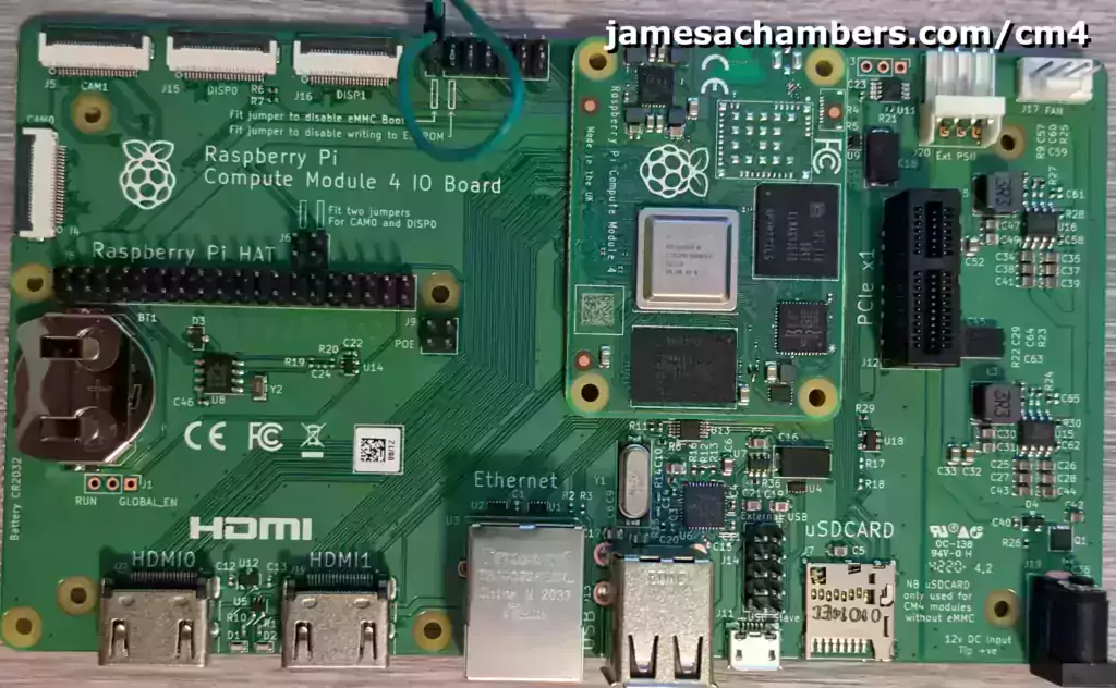
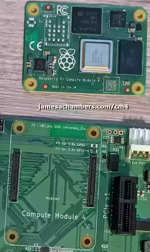
The Compute Module 4 by the Raspberry Pi Foundation is a single-board computer (SBC) that is meant to be used in embedded devices. It has many new capabilities that have not been seen on other Pis before such as a built in eMMC module (optional) and has PCI express capabilities when used with the IO board.
Links: Amazon.com*, AliExpress*, Amazon.ca*, Amazon.com.au*, Amazon.co.uk*, Amazon.de*, Amazon.es*, Amazon.fr*, Amazon.it*, Amazon.nl*, Amazon.pl*, Amazon.se*, Amazon.sg*
The “Raspberry Pi Compute Module 4 IO Board” is the most important one:
This is essentially the “motherboard” of the compute module. This IO breakout board lets us work with the compute module and get the ports we need to interface with it. This includes a SD card slot for models that don’t have eMMC, a PCI express slot (very exciting), 2 USB ports and more.
Links: Amazon.com*, AliExpress*, Amazon.ca*, Amazon.com.au*, Amazon.co.jp*, Amazon.co.uk*, Amazon.de*, Amazon.es*, Amazon.fr*, Amazon.it*, Amazon.nl*, Amazon.pl*, Amazon.se*, Amazon.sg*
There are also smaller and more purpose built boards (IO and otherwise) for the Compute Module 4 available but this is the one meant for development. The Compute Module 4 snaps into the IO board and becomes a part of it. Here’s what it looks like removed:
You will also need a power adapter. If you want to work with powerful NVMe drives or other power hungry PCI express technologies then I strongly recommend getting a full 12V DC adapter like this:

Delivers a full 12V DC to the IO board so that there’s enough power to run very powerful NVMe drives / accessories
Links: AliExpress*, Amazon.com*, Amazon.ca*, Amazon.com.au*, Amazon.co.jp*, Amazon.co.uk*, Amazon.de*, Amazon.es*, Amazon.fr*, Amazon.it*, Amazon.nl*, Amazon.pl*, Amazon.se*, Amazon.sg*
Here are the minimal power requirements. This power adapter will not give you much extra room for NVMe drives but the more power efficient ones will run from it. Highly recommend the bigger option.
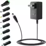
A generic 5V 3A power adapter designed to be in the safe range for the Raspberry Pi 3 / 4 / routers / USB hubs / other small electronics. Comes with different tips to fit different connections but the default connection (no tip) fits the IO board perfectly.
Links: Amazon.com*, Amazon.ca*, Amazon.sg*
You will need a data-transfer capable micro-USB cable to connect the IO board to your computer. Many of these are “charging only” cables since most things that use the data transfer use newer USB specs. Old cell phone cables are great bets here or you may have to try from a few cables you have. Worst case scenario here is one:
You will need jumpers. It can be the bridge style jumpers (often can be found on old motherboards, used for CMOS reset and the like) that are meant to jump two side by side or adjacent pins or you can use a breadboard female to female style jumper like this:

Female to female breadboard connectors
Links: Amazon.com*, AliExpress*, Amazon.ca*, Amazon.com.au*, Amazon.co.jp*, Amazon.co.uk*, Amazon.de*, Amazon.es*, Amazon.fr*, Amazon.it*, Amazon.sg*
The board does not come with a CR2032 battery unfortunately. These are pretty easy to find though as they are the same type of battery that will be in any old motherboard (the round silver CMOS backup battery).
Imaging Compute Module 4 eMMC
To image the Compute Module 4’s eMMC storage we will need to put the Compute Module 4 into “mass storage mode” by setting the J2 jumper like I have in my picture at the very top of the article (I have a wired jumper but normal jumpers that just bridge the J2 pin with the pin directly below it will work fine as well).
There’s one more step though before it will show up as a mass storage device. We need to get the rpiboot utility. Here’s what the utility will allow us to do:
Usage: rpiboot
then contain a initramfs to boot through to linux kernel

To flash the default bootloader EEPROM image on Compute Module 4 run
rpiboot -d recovery

For more information about the bootloader EEPROM please see:
https://www.raspberrypi.org/documentation/hardware/raspberrypi/booteeprom.md

rpiboot                  : Boot the device into mass storage device
rpiboot -d [directory]   : Boot the device using the boot files in 'directory'
Further options:
        -l               : Loop forever
        -o               : Use files from overlay subdirectory if they exist (when using a custom directory)
                           USB Path (1-1.3.2 for example) is shown in verbose mode.
                           (bootcode.bin is always preloaded-bash: Usage:: command not found
 from the base directory)
        -m delay         : Microseconds delay between checking for new devices (default 500)
        -v               : Verbose
        -s               : Signed using bootsig.bin
        -0/1/2/3/4/5/6   : Only look for CMs attached to USB port number 0-6
        -h               : This help
To get the utility follow the instructions for your OS below.
Instructions (Windows)
For Windows we need to download and install the following:
- The usbboot utility installer from the Raspberry Pi Foundations GitHub Repository: Official Raspberry Pi “usbboot” GitHub Repository
- The Raspberry Pi imager utility from the Pi downloads page: Raspberry Pi Official Software Download Page
Now you should have a new “Raspberry Pi” folder in your start menu that contains both the new usbboot utility and the Raspberry Pi imager utility like this:
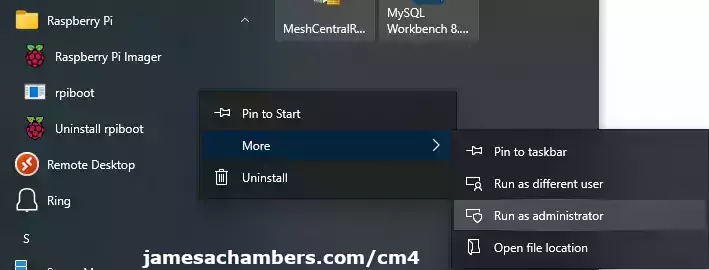
Open the “rpiboot” shortcut from the new “Raspberry Pi” start menu folder by right clicking and choosing “Run as administrator” from the “More” menu (like the above screenshot) and it should open a black console window like this:
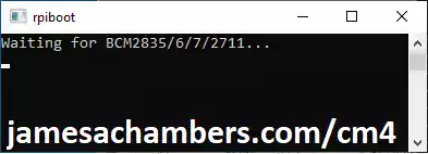
If you’ve set your jumper correctly for mass storage mode go ahead and connect the IO board’s micro-USB port (J19) to your PC and connect power to the IO board. You should see the following:
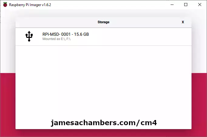
The window will disappear at this point and Windows will see the CM4’s onboard eMMC as a new mass storage device! Now open the Raspberry Pi Imager utility from the “Raspberry Pi” start menu folder. The CM4 will show up as a drive available to be imaged like this:
If your device wasn’t detected when you plugged in the power double check the following things:
- Try running it several times as sometimes the boot process seems to get “stuck” and then removing power from the IO board and starting the process over it will work the next time
- Try running as “Administrator” by going to the rpiboot shortcut in the “Raspberry Pi” start menu folder and right clicking on the shortcut and choosing More -> Run as Administrator
- You set the jumper located at “Fit jumper to disable eMMC boot” J2 (jumped with the pin directly below it)
- Check micro-USB cable type. Many of these cables are “charging only” and you need a micro-USB cable that is capable of data transfer. Ones from old cell phones are a great bet for this. Try some different cables if you aren’t sure if the one you are using has data transfer capabilities
- Check that the CM4 model is “snapped” into the board on both sides securely
- Make sure your model of CM4 actually has the eMMC (not all models do)
Instructions (Linux)
First install git, libusb, and make which are prerequisites:
sudo apt install git libusb-1.0-0-dev build-essential
Now clone the official Raspberry Pi usbboot utility’s repository and build the tool:
git clone --depth=1 https://github.com/raspberrypi/usbboot
cd usbboot
make
ls
You should now see the rpiboot utility in your current directory. You can install it system-wide with:
sudo make install
Whether you installed the utility system-wide or not it can now be used from the usbboot directory like this:
./rpiboot
If the Pi is connected and the jumper to disable eMMC booting is disabled (like in the picture at the top of this article) you should see the following output:
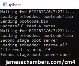
pi@pi:~/usbboot $ ./rpiboot
Waiting for BCM2835/6/7/2711...
Loading embedded: bootcode4.bin
Sending bootcode.bin
Successful read 4 bytes
Waiting for BCM2835/6/7/2711...
Loading embedded: bootcode4.bin
Second stage boot server
Loading embedded: start4.elf
File read: start4.elf
Second stage boot server done
We can verify that the device was mounted with:
ls /dev | grep "sd"
If you don’t have any other storage devices connected to the Pi this will usually be sda. If you do have other drives it will appear as a new entry like sdb, sdc, etc.
If you did not get the above output / your device wasn’t detected check the following:
- Try running it several times as sometimes the boot process seems to get “stuck” and then removing power from the IO board and starting the process over it will work the next time
- Try running as sudo (sudo ./rpiboot) to rule out anything like restrictive USB permissions for regular users and other configuration/environment restrictions
- Check that the CM4 model is “snapped” into the board on both sides securely
- Check micro-USB cable type. Many of these cables are “charging only” and you need a micro-USB cable that is capable of data transfer. Ones from old cell phones are a great bet for this. Try some different cables if you aren’t sure if the one you are using has data transfer capabilities
- Make sure your model of CM4 actually has the eMMC (not all models do)
Once you’ve determined the drive is mounted you can use the Raspberry Pi imager to image the device (if your distro has a GUI).
You may also directly image the eMMC using dd on the CLI like this:
sudo dd if=raw_os_image_of_your_choice.img of=/dev/sdX bs=4MiBAfter imaging is complete disconnect and reconnect the Pi so that the new partition table is read. You can now mount the partitions with:
cd /mnt
sudo mkdir boot
sudo mkdir root
sudo mount /dev/sdX1 /mnt/boot
sudo mount /dev/sdX2 /mnt/root
The first partition is the “boot” volume where config.txt and other files used during the boot process will be and the second partition is the “root” partition that contains the system and it’s files. You are now ready to configure the Compute Module 4!
Compute Module 4 Configuration
Now that you’ve finished imaging the module let’s make a few changes to make it more useful. Reconnect the Compute Module 4 to your computer using the USB cable (don’t remove the jumper from J2 disabling eMMC boot yet). Now that it is imaged you should see the “boot” volume where we can make some configuration changes.
Enable USB Ports
When mounted in the IO board the USB ports will not function without making a change to config.txt and adding an overlay.
Add the following line to config.txt:
dtoverlay=dwc2,dr_mode=host
After adding this line the two USB ports (as well as the “External USB” header) will function the next time the CM4 boots.
Enable SSH
It’s very useful to have SSH enabled when working with the Compute Module 4. It is enabled simply by creating an empty file named:
ssh
in the root folder of the “boot” volume (the top-most folder of the drive where start4x.elf, fixup.dat and those files are located).
Preconfigure WiFi / Wireless
You can also preconfigure the Compute Module 4 (and any Pi) by creating wpa-supplicant.conf at the base of the “boot” volume like we did with “ssh” file.
Create a new file named wpa-supplicant.conf that contains the following:
ctrl_interface=DIR=/var/run/wpa_supplicant GROUP=netdev
country=US
update_config=1

network={
 ssid="YourNetwork"
 psk="YourPassword"
}
When this file is created in the base of the “boot” volume it will automatically be applied to the Pi upon the next startup. Make sure to adjust your country=US line to your own country as this can impact what channels and functionality are available from your WiFi card!
Update Firmware
If you try to update the CM4’s firmware with the rpi-eeprom-update tool you will get the following message:
pi@raspberrypi:~ $ sudo rpi-eeprom-update
rpi-eeprom-update is not enabled by default on CM4. Run with -h for more information.
This is disabled by default because an invalid recovery.bin / if power is lost during an update it can cause you to have to restore the firmware using the rpiboot utility since the Pi will not be able to boot and you can’t remove the built in eMMC module like you can with a SD card.
We need to use the rpiboot utility to update the firmware. I will use the latest firmware at time of writing but check for the latest firmware at: rpi-eeprom-update Official Raspberry Pi Firmware Repository (if there is a newer one replace the pieeprom-2022-07-26.bin in the curl command below with the newer version file name).
Linux Firmware Update Instructions
This is meant to be done on your same PC we imaged the Pi with and not the Pi itself (unless you have Windows, in which case you will need to do these instructions on the Pi and copy the resulting “recovery” folder to Windows, see “Windows Firmware Update” section for more info).
cd ~/usbboot/recovery
rm -f pieeprom.original.bin
curl -L -o pieeprom.original.bin https://github.com/raspberrypi/rpi-eeprom/raw/master/firmware/stable/pieeprom-2022-07-26.bin
./update-pieeprom.sh
cd ..
./rpiboot -d recovery
(Optional) If you want to modify the bootloader’s config such as which device is the primary boot device as well as other bootloader parameters you can actually do so using this same process by editing boot.conf in the recovery folder like this:
cd ~/usbboot/recovery
nano boot.conf
./update-pieeprom.sh
Next make sure your Compute Module 4 IO board’s “disable MMC boot” jumper J2 is bridged with the lower pin to disable eMMC boot. Now connect the power:
pi@pi:~/usbboot $ ./rpiboot -d recovery
Loading: recovery/bootcode4.bin
Waiting for BCM2835/6/7/2711...
Loading: recovery/bootcode4.bin
Sending bootcode.bin
Successful read 4 bytes
Waiting for BCM2835/6/7/2711...
Loading: recovery/bootcode4.bin
Second stage boot server
Loading: recovery/config.txt
File read: config.txt
Loading: recovery/pieeprom.bin
Loading: recovery/pieeprom.bin
Loading: recovery/pieeprom.sig
File read: pieeprom.sig
Loading: recovery/pieeprom.bin
File read: pieeprom.bin
Second stage boot server done
That is it! It’s quite a pain, but it’s because the compute modules are designed to be updated once at deployment and shipped with a stock image. They aren’t meant to be updated in the field like regular Pis (at least the Pi’s core firmware) but they can still be updated using this process. After removing the “disable eMMC boot” jumper and rebooting the Pi the firmware will be updated!
You can verify this once you boot the Compute Module 4 by running rpi-eeprom-update again which should now look like this:
sudo CM4_ENABLE_RPI_EEPROM_UPDATE=1 rpi-eeprom-update

BOOTLOADER: up to date
   CURRENT: Tue 06 Jul 2021 10:44:53 AM UTC (1625568293)
    LATEST: Tue 06 Jul 2021 10:44:53 AM UTC (1625568293)
   RELEASE: stable (/lib/firmware/raspberrypi/bootloader/stable)
            Use raspi-config to change the release.

  VL805_FW: Using bootloader EEPROM
     VL805: up to date
   CURRENT:
    LATEST:
The firmware version for “CURRENT” should match the exact version you used for pieeprom.original.bin in our curl command regardless of what is available in the repository.
Windows Firmware Update Instructions
For Windows you will need to follow the Linux instructions to get rpiboot (and more importantly the configuration files/scripts) on your Pi to generate the new pieeprom files using the Pi. After following the Linux instructions all the way to the end we will then need to copy the “recovery” folder to Windows where we will be able to run the final command using the Command Prompt (make sure you are in the same directory you copied the “recovery” folder from Linux to before running) of:
"C:\Program Files (x86)\Raspberry Pi\rpiboot.exe" -d recovery
or you can fully qualify your paths with:
"C:\Program Files (x86)\Raspberry Pi\rpiboot.exe" -d "C:\YourPathTo\recovery"
and upon connecting the IO board (with USB mass storage boot disabled using the jumpers) the firmware will be updated!
The process will be exactly the same as Linux except for the very last step since you aren’t going to be able to plug the running Compute Module 4 IO board into itself to perform the final update using the “recovery” folder. This is extra work if you don’t have an additional Pi / Linux PC available you can plug the IO board into but it can be done!
First Boot
You are now ready to boot your Compute Module 4. Go ahead and remove the jumper now from J2 and the pin below it. If you’re using a monitor connect it to the IO board first.
Now connect power to the IO board and the eMMC boot process will start. Your OS should boot with your preconfigured settings!
Benchmarking / Testing Storage
Once you’ve booted up you can verify your drive’s performance using my storage benchmark with:
sudo curl https://raw.githubusercontent.com/TheRemote/PiBenchmarks/master/Storage.sh | sudo bash
If you search for the model of your drive / eMMC / etc. on Pi Benchmarks you can compare your score with others and make sure the drive is performing correctly!
Conclusion
The Compute Module 4 is really interesting and fun to work with. It’s still pretty difficult, time consuming (including in shipping) and expensive to get a hold of these but they are extremely cool.
A Compute Module 4 setup with an IO board is actually the most powerful Pi setup there is (including vs the Pi 400) because it has access to PCI express and NVMe storage. This is a game changer and has resulted in a higher class of performance (as seen on my pibenchmarks.com storage benchmark) than has ever been possible on the Pi before.
This is all in a package that is only slightly larger than a Pi Zero but has much greater capabilities. It’s also the first Pi to ever have a built in eMMC storage! There’s a lot happening with these devices and I would expect a lot of these capabilities to start showing up in other Pis as well.
Overall it’s definitely worth exploring them and getting a “Compute Module 4” setup going if you are a Pi / SBC enthusiast or want to build your own products powered by a Pi!
Other Resources
Definitely don’t miss my Shapes, Sizes and Features of Compute Module 4 IO Boards guide to see which IO boards may work best for your project
If you want to see how you can use real PCIe / NVMe on the Compute Module 4 check out my PCIe 1x NVMe Compute Module 4 guide
For an explanation of the Pico W (a microcontroller) check out my Pico W Explained article or if you want to jump right into the action and see what it’s like to work with a Pico check out my Pico W Getting Started guide


I cant boot and im using a bigtreetech pi4b adapter. I tried everything.
Hey Arthur,
Try using a different SD card. Whenever I get reports like this (and I get them for all types of boards I cover on the site) it’s usually the SD card. It’s not that the SD card is necessarily bad but there are compatibility issues with all boards with certain SD cards. If you have a different brand of SD card altogether you can try even better.
Sometimes it’s also the way the image is written. Did you completely extract the image file download before trying to write it to the SD card or did you try to write it as a compressed image without extracting it? What application did you use? Try it with something else. If it was Etcher use Win32DiskImager or try writing it with dd or one of the built-in imaging programs for Linux.
It can sometimes help to run the SD card association formatting tool. Etcher and other common programs people use for this don’t actually wipe the SD card. It’s extraordinarily hard to truly wipe a SD card unless you use the proprietary tools like the SD card association’s formatting tool.
This happens to me all the time. I have a stack of like a dozen SD cards from different brands and when it does I pick something completely different and try again and that almost always gets it. The least likely thing is that something is actually wrong with the hardware. It’s almost never that. It’s not impossible but my guess is one of those two things will probably take care of it.
It’s one of those things when you tell people that’s usually the cause they roll their eyes and think it’s impossible. It’s incredibly common though. If you have ever formatted that SD card with btrfs or any other type of unusual formatting in the past then that is 100% the problem and only running the SD card association’s tool will fix it (the exact same thing happens with the Raspberry Pi and it always has). SD cards have hidden partitions that are impossible to clear without using the manufacturer’s / SD card association’s tool. Formatting it with btrfs will burn it until it’s cleared with one of these tools.
Are you actually trying to use the CB1 or are you trying to use the real CM4 with the BTT Pi4B adapter? If you’re using a real CM4 with it I’ve actually never tried that before. I doubt that would work. I checked the Pi4B adapter’s Amazon reviews here and one of the sellers said this about using it with the real CM4:
Dear friendsthank you for your waiting ,it is suitable for it ,but it is need to upgraded the compiling firmware by yourself,if have any question ,you can send email to us
If you are trying to use the CM4 with this adapter board then it sounds like you’ll have to build some kind of firmware for it and flash it. Needless to say I don’t recommend that. I’ve only ever tried the CB1 with it and I would not have even expected it to work with the CM4.
It sounds like it’s theoretically possible according to the seller but definitely don’t try that. Get a different board actually meant for the CM4 like this one from Waveshare that is pretty similar. You basically have an I/O board meant for the CB1 and not the CM4. One actually meant for the CM4 only costs $1 more. Having to flash the firmware to get it working with a CM4 is not worth it if it requires compiling custom firmware for it.
Hopefully that helps!
Hi James,
Could you advise with the following issue i’m having, please?
My compute 4 and IO board were working fine, but now when i try to connect it to image the eMMC, the following appears;
RPIBOOT: build-date Feb 9 2023 version 20221215~105525 864863bcWaiting for BCM2835/6/7/2711...
Loading embedded: bootcode4.bin
Sending bootcode.bin
Successful read 4 bytes
Waiting for BCM2835/6/7/2711...
Loading embedded: bootcode4.bin
Second stage boot server
Cannot open file config.txt
Cannot open file pieeprom.sig
Loading embedded: start4.elf
File read: start4.elf
Cannot open file fixup4.dat
Second stage boot server done
This happens on both a windows PC and rpi 3.
Thank you in advance
Hey Lee,
It looks like it’s trying to boot to me. Do you have the jumper set on the board to disable eMMC boot? It looks like this:
This boot jumper can’t be set or you would not be seeing those messages since we can see it is trying to boot. When you set this jumper you will be able to image the eMMC and it won’t attempt to boot at all.
Hopefully that helps!
Hello, great article but I cannot get beyond a fatal error when I get to the first make step, I am using Ubuntu 22.04 on an intel cpu and getting
main.c:1:10: fatal error: libusb.h No such file or directory.
I already installed git, build essential, etc. no dice and I have searched the web for an answer but cannot resolve the problem, any thoughts?
Hey Tinker,
No worries at all, you’re incredibly close! There’s one more dependency that should take care of it for you:
sudo apt install git libusb-1.0-0-dev build-essentialThe libusb-1.0.0-dev should take care of it here!
Hi James, I appreciate the comment, as noted in my question I had already installed all of those. The good news is this time I did it with the most recent raspbian on a pi4 instead of Ubuntu on an intel cpu and the process worked perfectly. I just flashed the boot loader to the most recent and am currently installing an OS on the mmc. I am very pleased. Thanks again for the super useful article!
Hey Tinker,
No problem at all! I think the explanation for this is that the libusb-1.0-0-dev package has some other names on other flavors and older versions. For example my PopOS (Ubuntu-derived) 22.04 desktop has these options:
libusb-0.1-4/jammy 2:0.1.12-32build3 amd64userspace USB programming library
libusb-1.0-0/jammy-updates,now 2:1.0.25-1ubuntu2 amd64 [installed,automatic]
userspace USB programming library
libusb-1.0-0-dev/jammy-updates 2:1.0.25-1ubuntu2 amd64
userspace USB programming library development files
libusb-1.0-doc/jammy-updates 2:1.0.25-1ubuntu2 all
documentation for userspace USB programming
libusb-dev/jammy 2:0.1.12-32build3 amd64
userspace USB programming library development files
You can see how there’s a libusb-dev and that points to 2.0 now on the latest Ubuntu for example. Fortunately the libusb-1.0-0-dev package is still available on Ubuntu / PopOS 22.04 but you can see they’ve already jumped versions for the main libusb and it’s probably only a matter of time before the libusb-1.0-0-dev disappears from most up-to-date distros.
This is essentially the Linux version of dependency hell for sure. Eventually once the older 1.0 compatibility package starts being removed from the repositories of most Linux distributions it’s likely the Raspberry Pi foundation will update it to use libusb-2.0 (and in a perfect world they will do it before that).
I’m very glad you got it working, take care!
I’ve been experimenting with a Compute Module 4 on a Waveshare POE IO Board (B) booting from an M.2 SSD. My experiences and results of some stress testing here.
Hey Martin,
Very nice, I really like your test results measuring the power usage at idle at 3W to 5W at all CPU cores at 100%. I hadn’t seen that data before and that’s really interesting. Even more interesting is that you can get it up to 7W with the overclocks!
Thanks for sharing and take care!
other resources elsewhere on the web failed to mention the requirement to install build-essential, thanks for that – really appreciate it!
Thanks, appreciate the kind words and hearing that it’s helping. Take care!
Thanks for the inspiration to finally change BOOT_ORDER on my CM4. I documented the process – a real dog’s breakfast. Should it be possible to generate the pieeprom files with the python program (rpi-eeprom-config) under Windows 10? Avoiding the need for vcgencmd, etc?
Hey Bill,
You’re welcome and thanks for the feedback as well! I had tried a whole bunch of other methods to configure it and using the CM4’s rpiboot utility was the only way I could ever get anything to stick. I’m glad you met with success as well!
It’s theoretically possible to do it in Windows 10 with a Cygwin environment but the rpi-eeprom-config script I think is filled with warnings that it’s only supported to run on the Pi etc. but we really only want one specific function out of it that should work “offline” theoretically. This is mentioned a little bit here in the official Raspberry Pi documentation for setting up for Windows:
They don’t mention that you can use the update-pieeprom.sh portion on Windows but that you can build and use the tool on there for sure and a Cygwin environment (or equivalent) should give you the necessary utilities to generate the binaries. Basically the hangup would be that the binaries (the .bin file that gets flashed to your device) are generated by the script at the last line of this part of the Linux setup instructions:
cd ~/usbboot/recoveryrm -f pieeprom.original.bin
curl -L -o pieeprom.original.bin https://github.com/raspberrypi/rpi-eeprom/raw/master/firmware/stable/pieeprom-2021-07-06.bin
./update-pieeprom.sh
That update.pieeprom.sh script only consists of this:
#!/bin/sh# Utility to update the EEPROM image (pieeprom.bin) and signature
# (pieeprom.sig) with a new EEPROM config.
#
# pieeprom.original.bin - The source EEPROM from rpi-eeprom repo
# boot.conf - The bootloader config file to apply.
set -e
script_dir="$(cd "$(dirname "$0")" && pwd)"
${script_dir}/rpi-eeprom-config --config ${script_dir}/boot.conf --out ${script_dir}/pieeprom.bin ${script_dir}/pieeprom.original.bin
sha256sum ${script_dir}/pieeprom.bin | awk '{print $1}' > ${script_dir}/pieeprom.sig
echo "ts: $(date -u +%s)" >> "${script_dir}/pieeprom.sig"
As you can see there really isn’t a lot happening here except for the
rpi-eeprom-configcall but there is also a sha256sum ran. This would be included with virtually any distro (even Windows ones like Cygwin or the Linux Subsystem for Windows) but if you have a way to run bash/sha256sum and the Python script will allow itself to be executed in this way (or if you comment out/remove any safety checks complaining it’s not running on a Pi) then it may very well work!Maybe there’s some Pi-specific magic going on behind the scenes but I really think these are pretty simple operations as it uses the “.bin” file we download a couple lines before running the script so it’s not like it’s actually building a real binary from code or anything like that. It’s more like it’s “signing” it by adding in the bootloader parameters configured alongside the script in the folder and adding a sha256 signature etc. From this perspective it seems like you should be able to get this working with a basic Linux subsystem installed on Windows (as well as the right supporting Python libraries for it to be able to execute enough to run the one function we need)!
Thank you, once again James:
While a sha256 checksum is readily available in W10, rpi-eeprom-config would like to run vcgencmd. Difficult on anything but the target machine.
I’m glad to share my document with the commands and results, but it would be better as an attachment.
Would you appreciate a mention and link in RP org forums?
Regards, Bill
Hey Bill,
Dang, I knew I should have looked one level deeper in rpi-eeprom-config, that did cross my mind that it might call a proprietary-ish binary like vcgencmd! Another thought that crossed my mind that I didn’t mention is that VirtualBox running “Raspberry Pi Desktop” x86_64 should have those binaries for vcgencmd available still (not positive, but it seems like it would be crazy to not have x86 binaries available to communicate with Pis using a VM or desktop/etc). Since VirtualBox is free it might only take 10-15 minutes to set this up on a fast SSD.
I’m looking through the source though and vcgencmd is barely used at all. It’s only used to read the “current” bootloader config:
def read_current_config():Reads the configuration used by the current bootloader.
...
return (shell_cmd(['vcgencmd', 'bootloader_config']), "vcgencmd bootloader_config")
and that is only used by:
elif args.config is None and args.eeprom is None:current_config, config_src = read_current_config()
and
def edit_config(eeprom=None):...
if os.path.exists(pending):
config_src = pending
image = BootloaderImage(pending)
current_config = image.get_config().decode('utf-8')
else:
current_config, config_src = read_current_config()
These all look like they can be conditionally avoided (or the source modified to not allow that method to read the current config to ever be called). Maybe something like:
config_src = ''# If there is a pending update then use the configuration from
# that in order to support incremental updates. Otherwise,
# use the current EEPROM configuration.
bootfs = shell_cmd(['rpi-eeprom-update', '-b']).rstrip()
pending = os.path.join(bootfs, 'pieeprom.upd')
and modify the last line to:
pending = 'C:/path/to/usbboot/nvme/pieeprom.original.bin'theoretically. You can feel free to mention/link me for sure. If the Pi forums post has a picture with your results that would be great or you can link to it here as well!
Hi James:
I made a post to raspberrypi.org
You should be able to see my document there. Comments are certainly welcome.
Thanks again.
Hey Bill,
Everything is looking good! I did stop by and leave a comment and it was held in moderation for a while and finally got through. I think I was able to help fill in the dev on the situation as well. Thanks for putting that together!