
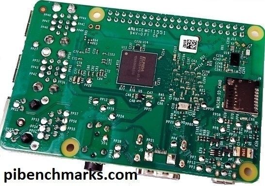
All of the previous generations of Raspberry Pi contained all of their firmware on the SD card. Starting with the Raspberry Pi 4 the device actually has onboard upgradable firmware stored on an EEPROM chip separate from your storage. Updating this firmware is very important as one of the first released updates reduces power usage of the Pi by 30% which also reduces how hot it gets.
In this guide I’ll show you how to update the bootloader firmware (no, it’s not apt-get upgrade, it’s a new utility called rpi-eeprom!) and also show you how to make a recovery SD card if your firmware gets corrupted and needs to be reflashed.
If you are looking for information on how to change the boot order on the Raspberry Pi 4’s new bootloader firmware, check out my New Raspberry Pi 4 Bootloader USB Booting Guide.
Upgrading the Bootloader Firmware
Requirements

The Raspberry Pi 4 is available in different memory configurations all the way up to 8 GB. It’s about the size of a credit card and uses an extremely low amount of power making it ideal for all sorts of projects and ideas!
Links: AliExpress*, Amazon.com*, Amazon.ca*, Amazon.com.au*, Amazon*.co.jp*, Amazon.co.uk*, Amazon.de*, Amazon.es*, Amazon.fr*, Amazon.it*, Amazon.nl*, Amazon.pl*, Amazon.se*, Amazon.sg*

The Raspberry Pi 400 kit includes everything you need for a full Pi 400 desktop build. The Pi 400 is the fastest Raspberry Pi ever released and comes in the form factor of a keyboard!
Links: AliExpress*, Amazon.com*, Amazon.ca*, Amazon.com.au*, Amazon.co.jp*, Amazon.co.uk*, Amazon.de*, Amazon.es*, Amazon.fr*, Amazon.it*, Amazon.nl*, Amazon.pl*, Amazon.se*, Amazon.sg*
To upgrade the firmware you should be running the latest Raspberry Pi OS. Do not attempt this from another distribution. If you want to use another distribution afterward that is great!
Since the Raspberry Pi bootloader firmware is stored on a chip on the device you can update it to the latest with Raspberry Pi OS and then go right back to using whatever you want. I personally have a separate SD card just for Raspberry Pi OS that I use to periodically plug in and update the firmware.
The firmware and the utilities around it are changing so quickly that you are really playing with fire not attempting this with the latest and greatest officially supported distribution when you are talking about firmware / on-board chips / etc.
With that word of caution out of the way, let’s get started!
Install rpi-eeprom (older versions of Raspberry Pi OS / Raspbian)
Newer versions of Raspberry Pi OS come with this utility already but if you are upgrading / have upgraded from an older version you may not have it in some cases. We can install it with the following commands:
sudo apt update
sudo apt full-upgrade
sudo apt install rpi-eeprom
Once the utility is installed Raspberry Pi OS will check at boot whether there are any critical bootloader firmware updates for your Pi.
Checking for Updates Manually
If you are like me and don’t want to wait around for Raspberry Pi OS to decide whether do these updates there is a command to check for updates manually:
sudo rpi-eeprom-updateYou will see output like this:
BCM2711 detected
VL805 firmware in bootloader EEPROM
BOOTLOADER: up-to-date
CURRENT: Thu 3 Sep 12:11:43 UTC 2020 (1599135103)
LATEST: Thu 3 Sep 12:11:43 UTC 2020 (1599135103)
FW DIR: /lib/firmware/raspberrypi/bootloader/critical
VL805: up-to-date
CURRENT: 000138a1
LATEST: 000138a1
If the firmware isn’t up to date it will indicate an update is required like this:
BCM2711 detected
VL805 firmware in bootloader EEPROM
*** UPDATE AVAILABLE ***
BOOTLOADER: update available
CURRENT: Thu 3 Sep 12:11:43 UTC 2020 (1599135103)
LATEST: Tue 24 Nov 15:08:04 UTC 2020 (1606230484)
FW DIR: /lib/firmware/raspberrypi/bootloader/beta
VL805: up-to-date
CURRENT: 000138a1
LATEST: 000138a1
We now can see that there is updated firmware for our device. To install this update we will use the -a switch as well as the -d switch (which means to check the bootloader):
sudo rpi-eeprom-update -d -a
If there were updates available your output should look like this:
BCM2711 detected
VL805 firmware in bootloader EEPROM
*** INSTALLING EEPROM UPDATES ***
BOOTLOADER: update available
CURRENT: Thu 3 Sep 12:11:43 UTC 2020 (1599135103)
LATEST: Tue 24 Nov 15:08:04 UTC 2020 (1606230484)
FW DIR: /lib/firmware/raspberrypi/bootloader/beta
VL805: up-to-date
CURRENT: 000138a1
LATEST: 000138a1
BOOTFS /boot
EEPROM updates pending. Please reboot to apply the update.
Reboot the Pi by typing sudo reboot and then run sudo rpi-eeprom-update again. This time it should tell you it is now up to date!
Changing rpi-eeprom’s Release Channel
By default you will only receive updates from Raspberry Pi OS “critical” channel. This is a very conservative firmware update channel that will only give you very well tested firmware updates that are considered critical fixes for the device. Another channel that is available is “stable”.
If you are trying to get USB boot support working and other recently added features I would try the “stable” channel first. It’s a lot more well tested and you’re less likely to run into any bleeding edge issues.
If you want to get the absolute latest firmware updates and fixes you may want to try the “beta” channel. These updates haven’t been tested as long and could potentially break your bootloader so Raspberry Pi OS only recommends using it if you are comfortable using the recovery tool to reflash your bootloader if something goes wrong. Check out the recovery section below for instructions on how to do this.
To switch to the beta channel we are going to edit the file /etc/default/rpi-eeprom-update:
sudo nano /etc/default/rpi-eeprom-update
Change the line FIRMWARE_RELEASE_STATUS=”critical” to:
FIRMWARE_RELEASE_STATUS="stable"
Or alternatively:
FIRMWARE_RELEASE_STATUS="beta"
Now you can run:
sudo rpi-eeprom-update -a
and you should see a new update available. You will need to reboot your Pi before the update is applied. I’d recommend rebooting it right away and run the check one more time and make sure it states you are now up to date.
View Bootloader Firmware Patch Notes
The latest official patch notes for all versions and changes are available in the rpi-eeprom GitHub repository
Disable Automatic Bootloader Firmware Updates
If you want to control when the updates are applied instead of leaving it up to Raspberry Pi OS the autoupdating service can be disabled with the following command:
sudo systemctl mask rpi-eeprom-update
The startup service has now been disabled and automatic bootloader firmware updates will only be applied if you do it manually.
To undo this and reenable the service we will use the unmask command:
sudo systemctl unmask rpi-eeprom-update
Now automatic firmware updates are enabled again!
Bootloader Recovery
The downside of having an onboard bootloader is that if something breaks reformatting your SD card will not fix it. In this section I will cover how to use the official tools to reflash and recover your Pi’s bootloader.
Requirements
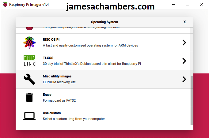
To do this we need to prepare a SD card with the Raspberry Pi 4 EEPROM boot recovery tool. The easiest way to do this is to use the official Raspberry Pi Imager tool from the Raspberry Pi foundation to prepare the recovery image.
Here is how we create the recovery image inside the utility. Choose the “Misc utility images” category as shown below:
Next choose the “Bootloader (restore the factory default settings and change boot priority)” option:
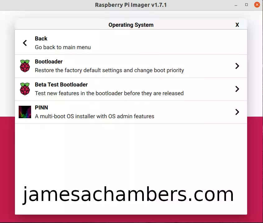
This will take you to a menu where you will select the default boot device for your Raspberry Pi like this:
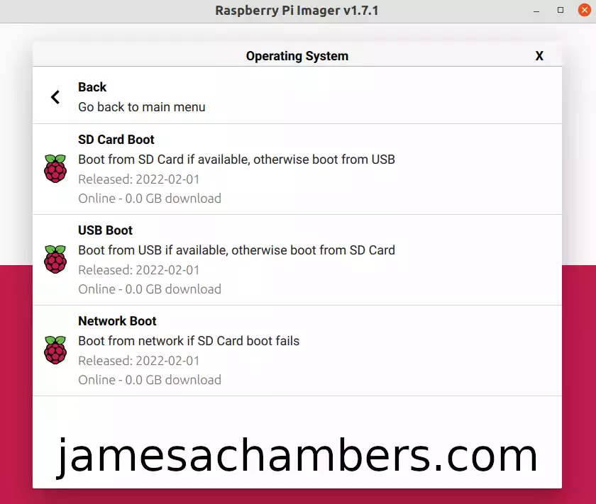
Notice that you are mostly just selecting the primary boot device. Modern versions of the firmware will fall back if the primary boot device fails. The first menu for example says “Boot from SD card if available, otherwise boot from USB”.
This means that if you took the SD card out you could still boot from a USB mass storage device if you selected the first option. Choosing the USB option would work similarly where if the USB mass storage boot failed it would fall back to booting from the SD card. Select the mode you would like and it should take you back to the main menu screen to pick the storage device to write to.
Next choose your SD card and then choose “Write”. Now unplug your Pi and put in the newly prepared SD card. Connect the power and let it boot. This will restore your bootloader to defaults. You should see a continuous rapid green blinking light. You may now disconnect the power and put your original SD card back / reinstall Raspberry Pi OS and boot the Pi normally!
When to Attempt Recovery
There is a simple procedure to tell if your bootloader is corrupt. Turn off your Pi completely and remove the SD card / all attached storage. Now plug your Pi back in with no storage media in it.
If your Pi’s bootloader is healthy you will see the green light blink a few times and then enter a pattern where it will blink 4 times and then have a long pause. It will repeat these 4 blinks / pause in an endless loop.
If your Pi’s bootloader is NOT healthy the green light will not blink. If this is the case it is time to do a bootloader recovery!
Another situation that can warrant a bootloader recovery is when your bootloader is missing a bunch of settings despite being up to date. For example other readers have seen cases where despite having the latest firmware according to rpi-eeprom-update they are missing key settings like the BOOT_ORDER setting. If anything is unusual with your settings many commenters have had success with this method when nothing else worked!
Recovery Procedure
Before powering up your device insert the “recovery” SD card that we made earlier in the requirements section above and make sure that all USB devices are removed. Even keyboards have been known to cause issues so make sure absolutely everything is unplugged!
Now insert the SD card into the Pi and connect the power.
If the bootloader recovery is successful the green activity light will start blinking rapidly continuously (forever). In this case you have successfully recovered your bootloader! You may now insert a normal fully imaged SD card and it will boot normally again.
If anything other than a continuous rapidly blinking green light happens the recovery was not successful.
If Recovery Doesn’t Work
- Try with a freshly imaged Raspberry Pi OS SD card. Sometimes there are unexpected things going on with an image that can prevent the newer firmware from being used (see next bullet point for example).
- Check your “boot” partition of your main OS and make sure there isn’t a file in there called “recovery.bin”. If this file is present it will load that version of the bootloader firmware instead of what is flashed on your Pi. This file should only be present on the “recovery” SD card we created but people are finding these files on their main OS “boot” partition. It’s worth checking to make sure it is not on the main OS SD card / drive you are trying to boot with.
- There is a known (and strange) issue with Raspberry Pi 4’s and 32 GB SD cards where the Pi will abort the boot. If this might apply to you then read this post.
- Make sure you created your SD card correctly. A common pitfall is using cards above 32 GB and formatting them with ex-FAT instead of regular FAT/FAT32.
- Make sure *all* USB devices are unplugged from the Pi
- Try a different SD card if you have one available. SD cards do go bad all the time. If there’s any doubt here check out my Raspberry Pi storage benchmarks page to see the highest performing SD cards (you definitely want an A1+ rated one).
- Check your power cord. Make sure you are using a high quality USB-C power cord that is compatible with the Pi. Even if it was working before I have had several old Pi power supplies that worked for years die on me. If there’s any doubt grab a known reliable one like the Canakit USB-C Raspberry Pi 4 Power Supply*
If you’ve gone through all the steps and are positive it’s not one of the above “gotcha” issues then it’s time to go deeper. You need to observe your Pi’s exact behavior when you plug it in (what the lights are doing). Here is a table of different blink patterns and what they mean:
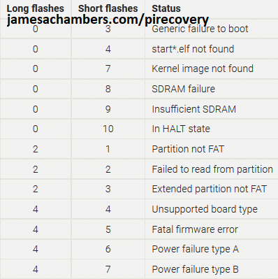
If your Pi’s LED behavior matches any of these codes then we now have much more to go on to diagnose why your Pi won’t boot. Some of them are very obvious but they’re all worth a quick web search once you have matched it to a code.
If your Pi’s behavior does not match one of these codes head to the official sticky post on the Raspberry Pi forums and scroll to the very bottom (post #4 specifically for Raspberry Pi). This tracks ongoing boot issues with the Pi 4 that may affect your Pi and a whole bunch of things to try. If you get through that post go all the way up to post #1 and start going down the list.
Could My Pi Be Dead?
It’s absolutely possible. Things like power issues (surges etc), wiring breadboards incorrectly, etc. can kill your Pi completely. That being said, if you have a Pi 4 that appears to be dead and you’ve gone through all my troubleshooting steps / the official sticky post / you aren’t covered by warranty then I would hold onto it for now as it’s still very new and some problems are still being investigated with the bootloader.
I have definitely killed a couple myself. I had a 3B+ that I had been using for a year building images (basically beating the crap out of it) on that finally had a hardware failure and would no longer boot. I wasn’t too sad about this one because I absolutely beat the crud out of these devices and push them to the absolute limit.
My more heartbreaking one was that I have killed a 4 GB Pi 4 that I got right at the Pi 4’s launch. I left this Pi in a very hot area running an experimental image that didn’t have proper firmware on it for about 2.5 weeks and now upon powering it up the green light will start blinking like it’s about to start booting then the green light will freeze and stay stuck on forever. I have a couple other Pi 4’s so I know all my cards and power supplies are good.
Make sure you’ve reviewed the official sticky post I linked in the previous section before jumping to this conclusion though. These things are not fragile and over all the years of running this blog it’s pretty amazing I’ve only killed 2 of them with the insane things I try on them all the time.
I may be able to help if you want to leave a comment here with *exactly* what behavior you’re seeing when you try these procedures, when you plug it in with no SD card in it, when you plug it in with a SD card in it, any little details will help!
Other Resources
For headless configuration of your Raspberry Pi using the Pi Imager
If you’re trying to setup USB mass storage booting (like with a SSD) check out my Raspberry Pi 4 Native USB Booting Guide
If you want to see which Pi storage performs the fastest and get an idea of what kind of drives to look for check out my 2020’s Fastest Raspberry Pi 4 Storage Benchmarks
If you have one of the new Raspberry Pi 400 kits *then don’t miss my Pi 400 Overclocking and SSD Setup Guide


Where can I find the eep Tom chip I lost its not on the board is it worth it buying it and soldering it on the board and where is it located.
Hi James,
I think my Pi 4B is dead but I hope it is not, it worked well some days ago to test Home Assistant, before I tried to “recycle” it as an OpenWRT router.
Flashed another microSD card with openWRT 22.03.2 (64bits) with the Pi Imager, inserted the card in the Pi, plug power … and only the red LED is on, nothing at all for the green LED (only a very short flash when I plug the power cord)
According to what I found here (and also on rpi docs and forums), the bootloader seems to be broken, because I get the same behavior when unplugging everything and without the microSD card.
I put the recovery image on the microSD card with the Pi Imager. But it does not work, I obtain the 4 short flashes on the green LED, and a red screen on HDMI0.
I’m like “ok, it does not found the start elf file, let’s get back with a regular image on the card” … but no, tried with rasberry pi os but it won’t boot, no green LED.
I don’t know what I can do more to recover the bootloader. I read somewhere that it is possible to get some debug data through the UART but maybe additional hardware is required ?
Hey Kistrof,
Welcome! So you’ve done some great testing here. This is an interesting case. Not too long ago I have a Raspberry Pi 4 that had a broken SD card slot. I let it sit for 2 years because I couldn’t do anything with it then one day I decided to try USB booting it. This worked on that one because I could still see the bootloader screen when starting up the Pi.
This one sounds different. The SD card slot sounds like it’s working. You’re actually the first person I have talked to that has got a red screen when doing the firmware recovery update. You definitely aren’t the first person *ever* to get it though fortunately!
Check out this post here:
my understanding is that recovery.bin isnt capable of bringing the dram online, and a red screen is shown if the flashing fails (either bad hash-check from SD, or error from spi chip)i have seen ~3-4 users, where the .sig file on the sd card never matches the .bin, and some have been able to recover using the CM4 reflashing tools, but the exact cause there is still a mystery
I agree with this person. This is probably a hardware issue. Either the SPI flash chip is bad or you might have one of these rare mismatched .sig issues (which would be good because there’s a chance of fixing that one). That brings us to your last question:
you will need to connect a 3.3v uart adapter to the gpio header to get any logs out of itYou’re right on the money here. The best thing for you to do would be to hook up a UART to TTY Serial USB adapter like this. This should let you at least see what the issue is and if it’s perhaps one of these mismatched signature issues.
Since the bootloader recovery is failing I think you should try this if you have one of the adapters. How you will need to proceed will depend on what that debug error message says. If it says mismatched signature you may be able to do the crazy CM4 recovery method to fix it they are alluding to in this post. I’ve never done that but I’m sure we can figure it out if you connect the UART adapter and it says that you do in fact have the mismatched signature issue!
I did some other tests, and I definitely think there is an hardware issue somewhere, because I let the Pi on with the recovery card, flashing with the 4-short code and the CPU is heating within some minutes.
I restarted the Pi (unplug-plug the power) and I got the recovery success, rapid flashing on the green led and a green screen ! Something like it works better when the Pi is hot.
I even succeeded to boot the Pi on a regular OS on a second SD card (swap the card with power on and unplug-plug the power). But after that, any other restart is failing as before 🙁
Also, today, even with a success recovery, restarting the Pi without any SD card does not produce the 4-short flashes code (it did yesterday when it was hot).
I don’t know if the eeprom is broken, or unavailable, or “forgot” its content within seconds, … I ordered a UART adapter (usb on one side, 4 pin connectors on the other side) so more tests to come for next week !
Erratum: I can obtain the 4-short flashes code without SD card, but the board has to be hot. I unplugged the power for 3 seconds and its behavior changed a little : the green led had less power and not flashing. Unplugged for 5 seconds, and it is dead again !
Hey Kistrof,
Fascinating! So I have seen something before like this here on the site a year ago. Check out the legend of Robocoder here.
In his case a resistor fell off the board. He did actually successfully repair this. In your case I think the only thing that can be happening here is that you have a very slightly loose chip (most likely) or potentially another part like a resistor as well. Why does this make sense? Because metal expands slightly when it’s hot. The only thing that makes sense to me is that you have a very slightly loose chip/component that is failing to make contact when the board is cold. When the board heats up the metal parts expand ever so slightly and the part in question must be making contact then.
It might be the EEPROM chip by the sound of it. Check out this forum post here of someone replacing that basically. It just sure sounds like it because if you are getting the 4 blinks when it’s warm it’s definitely running some kind of code. That code would be coming from the EEPROM chip (the boot loader) but it only seems to be getting there when it’s warm (and kind of intermittently).
I think the Pi probably sounds repairable. If it had a damaged CPU or something definitely not easily repairable like being fried this would not happen. If the temperature is impacting whether the board will boot or not this points to some chip or component being loose somewhere.
There’s a few ways you could test this theoretically. One easy way might be to physically press down on some of these chips when you’re trying to boot it. Literally try pressing down with your thumb (gently, it can’t be that loose if heating up is enough to bridge the gap) to make that contact artificially that is happening when the metal expands. If you press down on each one of these chips one at a time as you’re booting if you get lucky this might be enough to tell you which chip it is. With that knowledge you might literally just be able to hit the chip with a heat gun and then just press it down more securely. That might be enough to fix this.
It’s possible the EEPROM is bad as well. That could also explain the inconsistent behavior such as the EEPROM isn’t able to remember/retain anything. I really think you are onto something with the board temperature though and should try gently pressing and see if that will impact the behavior. If it won’t then soldering a new EEPROM chip like the forum post I linked may be in order (but I have high hopes it won’t come to that still unless you do further investigating and everything points toward that). It would be worth pressing on various chips around the board though other than the EEPROM chip as well though as we’ve seen other parts like resistors be the culprit as well like Robocoder’s incident.
Hopefully that helps!
Ok, I think I will burn that thing … Without any SD card, I have nothing at all on the serial output !
When booting on the eeprom flash image, I get this :
Read pieeprom.bin bytes 524288 hnd 0x00001b95 hash bb1b77f96cb69ba6Reading EEPROM: 524288
279025 bytes differ
Writing EEPROM
+sector-erase failed: 0x0 0xff
Partial update failed
Erasing EEPROM
chip-erase failed: 0xff
BOOT_ORDER: 0x1
SD HOST: 250000000 CTL0: 0x00000000 BUS: 100000 Hz actual: 100000 HZ div: 2500 (1250) status: 0x1fff0000 delay: 1080
SD HOST: 250000000 CTL0: 0x00000f00 BUS: 100000 Hz actual: 100000 HZ div: 2500 (1250) status: 0x1fff0000 delay: 1080
CID: 00035344534c31364780835d317a011c
CSD: 400e00325b59000076b27f800a404000
SD: bus-width: 4 spec: 2 SCR: 0x02358443 0x00000000
SD HOST: 250000000 CTL0: 0x00000f00 BUS: 12500000 Hz actual: 12500000 HZ div: 20 (10) status: 0x1fff0000 delay: 8
MBR: 0x00000800, 524288 type: 0x0c
MBR: 0x00000000, 0 type: 0x00
MBR: 0x00000000, 0 type: 0x00
MBR: 0x00000000, 0 type: 0x00
lba: 2048 oem: 'mkfs.fat' volume: ' NO NAME '
rsc 32 fat-sectors 4033 c-count 516190 c-size 1 r-dir 2 r-sec 0
WEL: 0x000027a2 0x000807ff
config.txt not found
No EEPROM files
Recovery failed
FATAL @ 0x800079e6 0x00000006 0x80003ee6
After warming up the thing, I get this :
Read pieeprom.bin bytes 524288 hnd 0x00001b95 hash bb1b77f96cb69ba6
Reading EEPROM: 524288

279025 bytes differ

Writing EEPROM

++++++++++++++++++++++..........+++++++++++++++++++++++++++++++++++++++++++++++++...............................................

Verify BOOT EEPROM

Reading EEPROM: 524288

0 bytes differ
And the rapid continuous led flashing
Then, as I said, I will probably try to heat it with something stupid 😉 (I don’t have any hot air welding station)
Hey Kistrof,
Yes, excellent, that does look pretty much like what we expected. We can see when it’s cold it can’t even erase the EEPROM chip. Once you warm it up you got:
Reading EEPROM: 524288279025 bytes differ
Writing EEPROM
++++++++++++++++++++++..........+++++++++++++++++++++++++++++++++++++++++++++++++...............................................
Verify BOOT EEPROM
Reading EEPROM: 524288
0 bytes differ
That 0 bytes differ is a successful flash. 0 bytes differ meaning it matches what it was expecting it to have. The + should indicate the parts of the flash chip that were modified. It’s interesting that most of the modifications seem to be at the beginning of the chip. I’d expect them to be toward the end of the chip where it’s making the modifications (or +) simply because when you do a full EEPROM flash it should start from the beginning and be incomplete/corrupt at the end.
This might indicate the EEPROM chip does in fact have some kind of fault as I’d expect losing contact during flashing to look like the opposite of this. It might just be that those sections of the EEPROM chip are actually bad especially if you try several reboots and the +’s are always in the same place. I would watch for this. Are the + in the same place on the writing EEPROM every time where it indicates it’s changing things? That would definitely suggest to me that those parts of the chip are bad if it’s always in the same place.
Then again this could be also explained by a partial erase failing (which we have seen in your other logs, it just says erase fails but maybe part of the erase is succeeding). If the erase is partially succeeding then failing half way through that may explain why all the +’s are at the beginning of the chip. I think the output confirms we are on the right track here but we can’t make a definitive conclusion yet about whether it’s the EEPROM chip itself that has failed or if this is a contact issue with the board (due to the heat changing the behavior still raising questions about what exactly is happening here and where).
The only question is whether this is a contact issue with the board or not. We know that heating it up is making the chip function correctly (at least in the examples you posted here). If this is due to bad contact with the chip to the board this could help. If the problem is inside the chip itself (like if the bad contact is within the chip instead of the chip making contact with the Pi/board) will probably need to be replaced.
A hair dryer might be the smarter way to go. My heat gun that I have and use pretty much is a hair dryer with a much narrower nozzle allowing me to direct the heat much more accurately than a hair dryer (which will probably heat the entire board realistically unless you cover the parts not being heated with a towel/cloth or something like that). It sounds just like one and it’s an extremely, extremely dry heat that kind of “smells” like a hair dryer. I don’t have a real fancy one either though. Mine is a <$11 heat gun from Amazon.
Then again my soldering iron is also a $20 one from Amazon and I’d probably really struggle to replace the EEPROM chip on my board without upgrading my tools to at the very least a modern soldering iron station (or at least it really would be a lot easier with one). I’d be able to reheat the chip and try pressing it more securely though with what I have though. I probably wouldn’t even try removing the EEPROM chip initially and would just heat it up and press down more securely (especially around the edges) to see if I can get the contact that is only happening when heated to make contact when cold (shouldn’t be too far). We’re just trying to nudge it slightly with this attempted fix and have it maintain that contact as it cools back down.
The next step would be taking it off the board and seeing if there’s some obvious reason this is happening underneath. Once you are pulling the chip off the board though it seems like you may as well replace it at that point though so the idea of trying the heat gun fix first is to potentially avoid having to completely remove and resolder the chip.
You have actually diagnosed this to the point where removal/inspection of the EEPROM chip is warranted here. We definitely have reason to believe it’s a hardware issue with the EEPROM chip. I would not blame you for wanting to try the reheat fix to see if we can nudge it back to working without having to go this far though. This is not a repair I would look forward to having to do and I too would try the easy fixes first for sure. I even saw someone mentioning they fixed something like this by running a toothbrush over all of front and back of the Pi. Somehow this presumably dislodged something that was causing some sort of short/problem and that’s another easy fix I would try before desoldering anything.
Definitely let us know what you find!
Hey James, I think I found the guilty part ! It seems to be the “big” A7W transistor next to the jack plug
I looked everywhere on the board to find anything weird, with a basic microscope, and this transistor seems to have at least 1 contact with a little crack between its “leg” and the pad.
Boot on recovery sd card succeed if I push on this transistor ! Even if a previous test without pushing it fails with “xxx bytes differ”, pushing it during the next test succeed with “no byte differ” !
I will try to heat it in order to fix its contacts with the board, but I doubt that a hair dryer is hot enough to melt the welds.
Hey Kistrof,
Great work! I see the hairline crack on the resistor leg you’re referencing. This makes perfect sense. It would have to be *tiny* for getting hot to bridge this gap and a hairline crack is indeed tiny enough for this to make sense. You’ve absolutely confirmed it by pressing on it which will make it fill that crack a little bit more from the pressure.
You’re right that a hair dryer won’t help with this one. The hair dryer can help with chips that are pressed into the board but this resistor is just held by the legs. It would fall off completely if the 3 solder points broke (at least they usually do and this has happened to people before where things completely just fell off the board). You definitely won’t be able to get the wires hot enough to fill the hairline crack. Everything else will likely start melting/warping before those contact plates will melt as they are meant to be soldered and can take the heat (but a lot of other parts around the board won’t be able to).
It’s presumably heat that did this in the first place. That type of cracking is what I would expect to see when a metal that has some sort of structural weakness in it is heated and cooled over and over again. It could have also just happened randomly but my guess is there was some kind of underlying weakness / defect in the metal that cracked due to heating/cooling over time.
This is a job for solder. If you have a super cheap soldering iron like me (anything will do) what you may want to do is just fill that tiny crack with a little tiny bit of solder melted into it. The hot solder will absolutely fill that gap. You shouldn’t need to remove the resistor to do this fix. We just need to patch the hairline crack with a tiny bit of solder most likely. If everything else feels / looks secure that should probably take care of this one permanently.
Less is more when doing this fix. You don’t want to bridge anything else by using too much. Just a little tiny bit of hot solder melted into that tiny crack should permanently fill that gap at any temperature. Soldering will be a permanent fix for this and will prevent it from getting any worse (such as the crack / gap widening over time to the point where being hot is no longer enough to bridge it).
I know it may not be the best news if you don’t have any soldering iron at all on hand but to be honest with you I think this is a pretty lucky outcome compared to some of the alternatives (which like I was saying if it was some of the worst case scenarios I would have personally upgraded my tools before even attempting some of the worst things it could have been).
The cheapest iron you can find with the small bundled sampler solder it comes with should be enough for this as we just need to fill that crack/gap with something conductive since realistically this is probably a break (or it’s hanging by a thread and a gust of wind could cause it to break altogether).
It’s likely the other two arms that are holding everything together where it just looks like a crack but if they weren’t it has probably already broken would be my guess but since it is in fact being held in place by the other 2 arms it’s touching and completing the connection when hot. It would be like holding a broken plate together. You can make the cracks look pretty tiny when it’s being supported but without you holding it in place it would fall to pieces immediately. Soldering it will basically fill that gap and additionally add a whole additional layer of metal and structural support to where you apply it so things hold together securely going forward (assuming the other two arms remain in place securely which they probably will).
Great work narrowing this down, let us know how it goes and what you end up doing to fill / fix the crack!
Hello, my old solder iron is very bad, I think it does not heat enough, so the result is pretty bad and it is not fixed.
But I discovered that pushing on this component is not the only way to make it work, simply bend the board is also workink, ie. by pushing on the jack connector.
I will not work on it for some weeks, and probably buy an hot air station with some weld stuff to remake that the good way, and much cleaner !
Hey Kistrof,
Ahh yes that sounds like a tricky one. I don’t blame you for wanting to get better tools before attempting this again.
Bending the board won’t help us figure out which component is loose really. No matter which one it is bending the board will likely work. Bending the board will flex *all* of the connections basically. It could be anywhere because bending the board will impact all circuits.
I hope the board isn’t cracked as that is one possibility. If it was though you trying to bend it would have probably snapped it. It’s probably still what we originally thought it was.
The best way to diagnose this would be to gently press each one one at a time. I know we’ve kind of done this already though. The lightest touch should be used. If you bend/flex the board it completely invalidates the test. If you press hard enough on the chip to bend the board that will also invalidate the test. If you press hard on any chip you will get it to do this because you are actually bending the board at that point (in a very harmful way, from a pressure point). You want to barely touch it. You want to almost let the weight of your finger be the test. If you press it will flex the board and you’ll have no idea which component it is.
The other way would be to really thoroughly go over this board with the scope again for sure. I think if you have the right tools to do this it will be easy. I definitely 100% agree with your idea of waiting until you have better tools. I’m certain you can fix this board unless it does turn out to be something crazy like a PCB crack. If I had tried my solder iron and had the same experience you did I would have done the exact same thing as you (which I kind of hinted at too). If I started to make a mess I would have known I need to upgrade my station and a day will come when that happens for me as well.
Definitely keep me updated once you get some tools to do this. I’m really interested as this is a tough case but it seems so close to fixable!